Honda Ridgeline. Manual - part 21


  Index      Honda     Honda Ridgeline - service repair manual 2006-2008 year


Search            


Content   ..  19  20  21  22   ..


Honda Ridgeline. Manual - part 21


SJC8A00A14500000000HBAT01
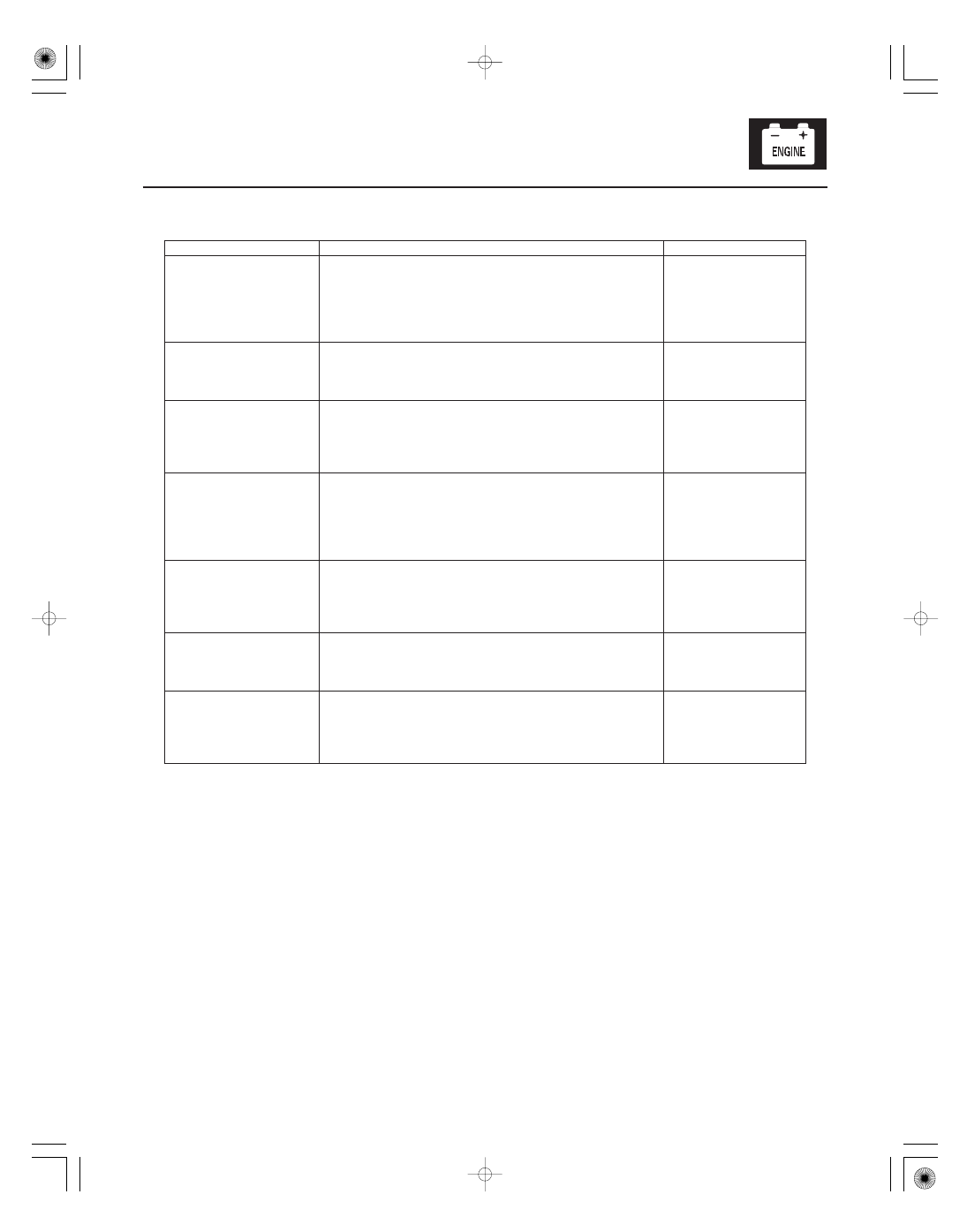
Symptom

Diagnostic procedure

Also check for

4-41

Symptom Troubleshooting Index

Cruise control cannot be
set

1.
2.

3.
4.

Check for PGM-FI and body DTCs.
Check the No. 13 (20 A) fuse in the under-hood fuse/
relay box, and No. 18 (15 A) fuse in the under-dash fuse/
relay box.
Do the cruise control input test (see page 4-44).
Do the cruise control main switch test (see page 4-46).

Cruise control can be set,
but the cruise control
main switch indicator
does not come on

1.
2.

Do the cruise control main switch test (see page 4-46).
Check for a faulty cruise control main switch
illumination bulb.

Faulty cruise control
main switch

Cruise control can be set,
but the cruise control
indicator does not come
on

1.
2.

3.

Check for PGM-FI and body DTCs.
Do the gauge control module self-diagnostic function
(see page 22-244).
Do the cruise control input test (see page 4-44).
Test the cruise control indicator signal input.

Faulty gauge control
module

Vehicle does not
decelerate or accelerate
accordingly when the set/
decel or resume/accel
switch is pressed

1.
2.

3.

Check for PGM-FI and body DTCs.
Do the cruise control input test (see page 4-44).
Test the cruise control set/decel, resume/accel switch
signal input.
Do the cruise control set/decel, resume/accel, cancel
switch test (see page 4-46).

Open circuit, loose or
disconnected
terminals: GRY/RED or
LT GRN/BLK

Set speed does not
cancel when the brake
pedal is pressed

1.
2.

3.

Check for PGM-FI and body DTCs.
Do the cruise control input test (see page 4-44).
Test the brake pedal position switch signal input.
Do the brake pedal position switch test (see page
22-174).

Short to power on
the BRN/YEL wire
Faulty brake pedal
position switch

Set speed does not
cancel when the cruise
control main switch is
pressed

1.
2.

3.

Check for PGM-FI and body DTCs.
Do the cruise control input test (see page 4-44).
Test the cruise control main switch signal input.
Do the cruise control main switch test (see page 4-46).

Short to power on the
LT GRN wire

Set speed does not
cancel when the cancel
switch is pressed

1.
2.

3.

Check for PGM-FI and body DTCs.
Do the cruise control input test (see page 4-44).
Test the cruise control cancel switch signal input.
Do the cruise control set/decel, resume/accel, cancel
switch test (see page 4-46).

Open circuit, loose or
disconnected
terminals: GRY/RED or
LT GRN/BLK

(cont’d)

Symptom

Diagnostic procedure

Also check for

4-42

Cruise Control

Symptom Troubleshooting Index (cont’d)

Set speed will not
resume when the
resume/accel switch is
pressed (with the cruise
control main switch
turned on, and set speed
temporarily canceled by
pressing the brake pedal)

1.
2.

3.

4.

Check for PGM-FI and body DTCs.
Check the brake pedal position switch adjustment
(see page 19-6).
Do the cruise control input test (see page 4-44).
Test the cruise control resume/accel switch signal input.
Test the brake pedal position switch signal input.
Do the cruise control set/decel, resume/accel, cancel
switch test (see page 4-46).

Faulty brake pedal
position switch
Open circuit, loose or
disconnected
terminals:
LT GRN/BLK

With the ignition switch
ON (II), and the lighting
switch turned on, the
cruise control main
switch illumination does
not come on

1.

2.

Replace the cruise control main switch illumination
bulb (see page 4-46).
Do the cruise control main switch test (see page 4-46).

With the ignition switch
ON (II), and the lighting
switch turned on, the
cruise control set/decel,
resume/accel, cancel
switch illumination does
not come on

Replace the cruise control set/decel, resume/accel, cancel
switch (see page 4-46).

*01

SJC8A00A14500000000EAAT00

4-43

Circuit Diagram

4

3

1

2

5

6

N29

X1

F19

D10

A6

A1

A36

C4

A20

B3

A6

A7

A8

SG

THL2

THL1

VCC

ETCSM

ETCSM

ATPFWD

NC

A8

A1

A14

C20

C1

A12

A13

7

6

3

3

6

7

2

1

2

1

J4

H9

H1

BLU/RED

HORN

F17

E10

X8

E6

G1

D9

INDICATOR

(15 A)

No.8

BLK/YEL

WHT

BLK/YEL

YEL/BLK

LIGHTS

RED/BLU

LT GRN/BLK

5

4

7

6

RED/BLK

RED/BLK

CABLE
REEL

GRY/YEL

HORN

BLU/RED

No.23
(IG)
(50 A)

(120 A)

LIGHT

CRUISE CONTROL INDICATOR

CRUISE DIMMING CIRCUIT

DRIVE CIRCUIT

POWER SUPPLY/CONTROLLER AREA NETWORK CONTROLLER

GRY/RED

LT GRN/BLK

THROTTLE BODY

TP SENSOR

GRN

RED/BLU

RED/BLK

BLU

GRN

BLU

CANL

RED

5 V

IGP1

YEL/BLK

BLK/YEL

BLK/YEL

B19

B17

C2

MRLY

PCM

12 V

5 V

RED/YEL

BRN/YEL

WHT/GRN

YEL/BLK

HORN RELAY

IG1

BAT

2

1

WHT

YEL/GRN

C17

B40

B34

B12

ETCSRLY

GAUGE CONTROL MODULE

BRN

2

1

4

3

G401

WHT/BLK

RED

RED/BLU

GRY/RED

(15 A)

No.18

GRY/YEL

(BAT)

No.22

No.9 (15 A)

UNDER HOOD FUSE/RELAY BOX

BATTERY

No.13 (20 A)

3

3

1

BLK/YEL

RED/BLK

RED

BLK

LT GRN

2

5

4

CANH

IG1ETCS

BKSWNC

BKSW

C3

BLU

BLU/YEL

REEL

CABLE

IG1 HOT in ON (II)
and START (III)

CRUISE CONTROL
MAIN SWITCH

THROTTLE
CONTROL
RELAY

BRAKE
PEDAL
POSITION
SWITCH

THROTTLE
ACUTUATOR

OUTPUT SHAFT
SPEED SENSOR

TRANSMISSION
RANGE SWITCH

SET/
DECEL

CAN
CEL

RESUME/
ACCEL

IGNITION
SWITCH

PGM FI
MAIN
RELAY 1

HORN
SWITCH

TAILLIGHT
RELAY

TAILLIGHT
RELAY

CRUISE CONTROL
SET/DECEL,
RESUME/ACCEL
CANCEL SWITCH

UNDER DASH
FUSE/RELAY
BOX

RELAY
CONTROL
MODULE

2

6

SJC8A00A14500000000FCAT00

Signal to be tested

Parameter: Desired result

Test condition

Possible cause if result is not obtained

4-44

Cruise Control

Cruise Control Input Test

1. Connect the Honda Diagnostic System (HDS) to the data link connector (DLC) (see step 2 on page 11-3).

2. Turn the ignition switch ON (II).

3. Go to PGM-FI, and check for DTCs.

4. Do the following tests while monitoring parameters in the PGM-FI DATA LIST with the HDS.

NOTE: Intermitent failures are often caused by loose circuit connections. While monitoring cruise control inputs,
flex their circuits, and note if any of the test results change.


Brake switch
signal

Brake pedal pressed,
then released

CRUISE BRAKE SW
should indicate OFF
when the brake pedal is
pressed and ON when
the brake pedal is
released.

Faulty brake pedal position switch
Blown No. 18 (15 A) fuse in the under-
dash fuse/relay box
An open in the wire between the
powertrain control module (PCM) and
the brake pedal position switch
A wire shorted to ground between the
PCM and the brake pedal position switch

Transmission
range switch
signal

Shift lever in D

SHIFT/CLUTCH SW
should indicate ON in P,
R, N, 2, and 1 and OFF
in D.

Faulty transmission range switch
An open in the wire between the PCM
and the transmission range switch
A wire shorted to ground between the
PCM and the transmission range switch
Poor ground G101 and G102

Cruise control
main switch
signal

Cruise control main
switch ON and OFF

CRUISE CONTROL
MAIN SW should
indicate ON when the
cruise control main
switch is turned ON
and OFF when the
cruise control main
switch is turned OFF.

Faulty cruise control main switch
An open in the wire between the gauge
control module and the cruise control
main switch
A wire shorted to ground between the
gauge control module and the cruise
control main switch
An open in the wire between the cruise
control main switch and ground

Set switch
signal

Set/decel switch
pressed and released

CRUISE CONTROL SET
SW should indicate ON
when the set/decel
switch is pressed and
OFF when the set/decel
switch is released.

Faulty cruise control set/decel, resume/
accel, cancel switch
An open in the wire between the gauge
control module and the cruise control
set/decel, resume/accel, cancel switch
A wire shorted to ground between the
gauge control module and the cruise
control set/decel, resume/accel, cancel
switch


Content   ..  19  20  21  22   ..