Honda Ridgeline. Manual - part 20


  Index      Honda     Honda Ridgeline - service repair manual 2006-2008 year


Search            


Content   ..  18  19  20  21   ..


Honda Ridgeline. Manual - part 20


02

03

04

05

Special Tools Required

Alternator Disassembly

4-37

A

B

A

B

A

• Driver 07749-0010000
• Attachment, 42 x 47 mm 07746-0010300

NOTE: Refer to the Exploded View as needed during
this procedure.

1. Test the alternator and regulator before you

remove them (see page 4-28).

2. Remove the alternator (see page 4-34).

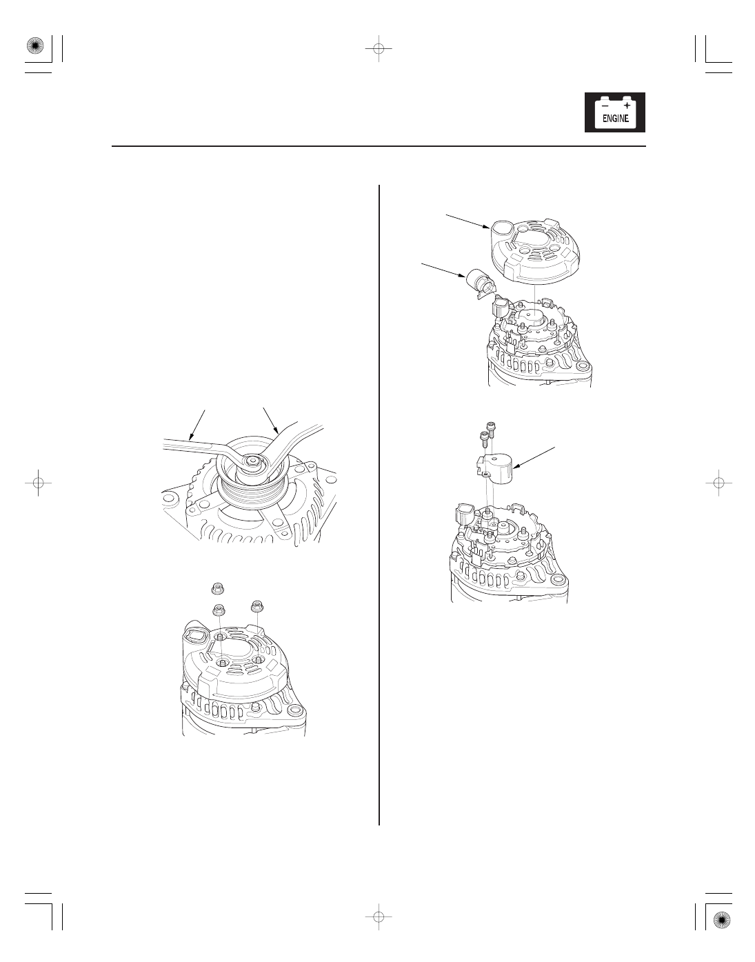
3. If the front bearing needs replacing, remove the

pulley locknut with a 10 mm wrench (A) and a
22 mm wrench (B). If necessary, use an impact
wrench.

4. Remove the three flange nuts.

5. Remove the end cover (A) and the insulator (B).

6. Remove the brush holder (A).

(cont’d)

06

07

08

09

4-38

Charging System

Alternator Overhaul (cont’d)

A

B

7. Remove the four bolts, then remove the rear

housing assembly (A) and washer (B).

8. If you are not replacing the front bearing, go to

step 13. Remove the rotor from the drive-end
housing.

9. Inspect the rotor shaft for scoring, and inspect the

bearing journal surface in the drive-end housing for
seizure marks.

• If the rotor is damaged, replace the rotor

assembly.

• If the rotor is OK, go to step 10.

10. Remove the front bearing retainer plate.

11. Drive out the front bearing with a brass drift and

hammer.

10

11

12

Alternator Brush Inspection

Alternator Brush Length
Standard (New): 10.5 mm (0.41 in.)
Service Limit:

1.5 mm (0.06 in.)

Rotor Slip Ring Test

4-39

07749-0010000

07746-0010300

B

A

A

B

C

12. Install a new front bearing in the drive end housing

with a hammer, driver handle, and attachment.

13. Measure the length of both brushes (A) with a

vernier caliper (B).

• If either brush is shorter than the service limit,

replace the brush holder assembly.

• If the brush length is OK, go to step 14.

14. Check for continuity between the slip rings (A).

• If there is continuity, go to step 15.
• If there is no continuity, replace the rotor

assembly.

15. Check for continuity between each slip ring and the

rotor (B) and the rotor shaft (C).

• If there is no continuity, replace the rear housing

assembly, and go to step 16.

• If there is continuity, replace the rotor assembly.

16. Assemble the alternator in the reverse order of

disassembly, and note these items:

• Be careful not to get any grease or oil on the slip

rings.

• If you removed the pulley, tighten its locknut to

110 N·m (11.2 kgf·m, 81.0 lbf·ft) when you
reinstall it.

*01

*02

SJC8A00A14500000000DAAT00

4-40

Cruise Control

Component Location Index

BRAKE PEDAL POSITION SWITCH

CRUISE CONTROL INDICATOR
(Built into gauge control module)

CRUISE CONTROL
SET/DECEL, RESUME/ACCEL,
CANCEL SWITCH

CRUISE CONTROL MAIN SWITCH

TRANSMISSION RANGE SWITCH

POWERTRAIN CONTROL MODULE (PCM)

Test, page 22-174
Pedal Height Adjustment, page 19-6

Test/Replacement, page 4-46

Test/Replacement, page 4-46

Test, page 14-272
Replacement, page 14-273

Cruise Control Input Test, page 4-44


Content   ..  18  19  20  21   ..