Honda Odyssey 2004. Manual - part 606


  Index      Honda     Honda Odyssey 2004 - service repair manual 2004 year


Search            


Content   ..  604  605  606  607   ..


Honda Odyssey 2004. Manual - part 606


*02

14

*03

16

YES

NO

YES

NO

23-366

SRS

Symptom Troubleshooting (cont’d)

C851

A

SRS MAIN HARNESS 28P CONNECTOR

BLU

BLU

GAUGE ASSEMBLY CONNECTOR C (16P)

C503

BLU

BLU

GAUGE ASSEMBLY CONNECTOR C (16P)

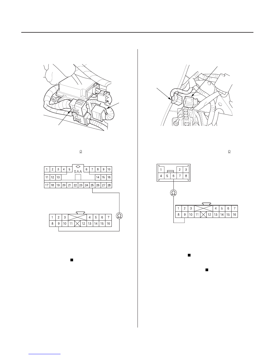
5. Disconnect SRS main harness 28P connector (A)

from the SRS floor harness connector C851.

6. Check resistance between the No. 9 terminal of

gauge assembly connector C (16P) and the No. 25
terminal of SRS main harness 28P connector .
There should be 0

1.0

.

Open in the SRS floor harness; replace the

SRS floor harness.

Go to step 7.

7. Disconnect the dashboard wire harness 8P

8.

gauge assembly connector C (16P) and the No. 6

0

1.0

.

Open in the SRS main harness; replace the

SRS main harness.

Open in the dashboard wire harness; replace

the dashboard wire harness.

Wire side of female terminals

Wire side of female terminals

Wire side of female terminals

Terminal side of
male terminals

Is the r esistance as specif ied?

Is the r esistance as specif ied?

03/07/29 10:42:41 61S0X050_230_0366


terminal of the dashboard wire harness 8P

connector C503 from the SRS main harness (A).

Check resistance between the No. 9 terminal of

connector C503. There should be

DASHBOARD WIRE HARNESS 8P CONNECTOR C503

A

S0X4A00H46400000000MDAT00

’99-01 Models

’02 Model

’99-02 Models

’03-04 Models

’03-04 Models

23-367

Component Replacement/Inspection After Deployment

NOTE: Before doing any SRS repairs, use the HDS
method to check for DTCs; refer to the DTC
Troubleshooting Index for the less obvious deployed
parts (seat belt tensioners, front sensors, side airbag
sensors, etc.).

After a collision where the front airbags deployed,
replace these items:

• SRS unit
• Airbags
• Seat belt tensioners

After a collision where the seat belt tensioners
deployed, replace these items:

• Seat belt tensioners
• SRS unit
• Front sensors

After a collision where the front airbag(s) deployed,
replace these items:

• SRS unit
• Deployed airbag(s)
• Seat belt tensioners
• Front sensors

After a collision where the side airbag(s) deployed,
replace these items:

• SRS unit
• Deployed side airbag(s)
• Side impact sensor(s) for side(s) deployed

During the repair process, inspect these areas:

• Inspect all the SRS wire harnesses. Replace, don’t

repair, any damaged harness.

• Inspect the cable reel for heat damage. If there is any

damage, replace the cable reel.

After the vehicle is completely repaired, turn the
ignition switch on. If the SRS indicator comes on for
about 6 seconds and then goes off, the SRS airbag
system is OK. If the indicator does not function properly,
use the HDS to read the DTC(s). If this doesn’t retrieve
any codes, use the Tester’s SCS menu method. If the
SCS method doesn’t work, you may need to install a
known-good SRS unit to read the DTC(s). If you still
cannot retrieve a code, go to SRS Indicator Circuit
Troubleshooting.

After a collision where the seat belt tensioners
deployed, replace these items:

• Seat belt tensioners
• SRS unit
• Front sensors

After a collision where the front airbag(s) deployed,
replace these items:

• SRS unit
• Deployed airbag(s)
• Seat belt tensioners
• Front sensors

After a collision where the side airbag(s) deployed,
replace these items:

• SRS unit
• Deployed side airbag(s)
• Side impact sensor(s) for side(s) deployed

During the repair process, inspect these areas:

• Inspect all the SRS wire harness. Replace, don’t

repair, any damaged harness.

• Inspect the cable reel for heat damage. If there is any

damage, replace the cable reel.

The operation of the front passenger’s weight sensor
unit (see page 23-42) must be checked after any of
these actions.

• Replacement of front passenger’s seat component(s)
• After a vehicle collision

After the vehicle is completely repaired, turn the
ignition switch on. If the SRS indicator comes on for
about 6 seconds and then goes off, the SRS airbag
system is OK. If the indicator does not function properly,
use the HDS to read the DTC (see page 23-38).

03/07/29 10:42:41 61S0X050_230_0367

01

02

01

02

S0X4A00H46400012802KBAT00

Removal (’99-01 Models)

Removal (’02-04 Models)

23-368

SRS

Driver’s Airbag Replacement

C

A

B

D

B

A

C

C

B

A

B

A

1. Disconnect the battery negative cable, and wait at

least 3 minutes before beginning work.

2. Remove the access panel (A) from the steering

wheel, then disconnect the connector between the
cable reel 2P connector (B) and the driver’s airbag
2P connector (C).

3. Remove the covers (A, B) from the steering wheel,

remove the two Torx bolts (C) using a Torx T30 bit,
then remove the driver’s airbag (D).

4. Disconnect the horn connector from the steering

wheel.

1. Disconnect the battery negative cable, and wait at

least 3 minutes before beginning work.

2. Remove the access panel (A) from the steering

wheel, then disconnect the connector between the
cable reel 4P connector (B) and the driver’s airbag
4P connector (C).

3. Remove the two Torx bolts (A) using a Torx T30 bit,

then remove the driver’s airbag (B).

03/07/29 10:42:42 61S0X050_230_0368

*01

04

03

04

Installation (’99-01 Models)

Installation (’02-04 Models)

23-369

C
9.8 N·m
(1.0 kgf·m, 7.2 lbf·ft)

D

D

B

A

B

C

A

B
9.8 N·m
(1.0 kgf·m, 7.2 lbf·ft)

A

B

A

C

1. Reconnect the horn connectors (A), then place the

new driver’s airbag (B) in the steering wheel, and
secure it with new Torx bolts (C). Install the covers
(D).

2. Connect the cable reel 2P connector (A) to the

driver’s airbag 2P connector (B), then install the
access panel (C) on the steering wheel.

3. Connect the battery negative cable.

4. After installing the airbag, confirm proper system

operation:

• Turn the ignition switch ON (II); the SRS indicator

should come on for about 6 seconds and then go
off.

• Make sure the horn button works.

1. Place the new driver’s airbag (A) in the steering

wheel, and secure it with new Torx bolts (B).

2. Connect the cable reel 4P connector (A) to the

driver’s airbag 4P connector (B), then install the
access panel (C) on the steering wheel.

3. Connect the battery negative cable.

4. After installing the airbag, confirm proper system

operation:

• Turn the ignition switch ON (II); the SRS indicator

should come on for about 6 seconds and then go
off.

• Make sure the horn button works.

03/07/29 10:42:44 61S0X050_230_0369


Content   ..  604  605  606  607   ..