Honda Odyssey 2004. Manual - part 600
−
−
−
−
−
04
10
05
02
YES
NO
YES
NO
23-342
SRS
Symptom Troubleshooting (cont’d)
A
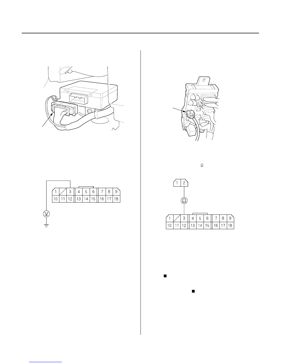
SRS MAIN HARNESS 18P CONNECTOR
A
SRS MAIN HARNESS 2P CONNECTOR
SRS MAIN HARNESS
18P CONNECTOR
19. Disconnect the SRS main harness 18P connector
(A) from the SRS unit.
20. Reconnect the battery negative cable.
21. Connect a voltmeter between the No. 3 terminal of
SRS main harness 18P connector and body ground.
Turn the ignition switch ON (II), and measure the
voltage. There should be battery voltage.
Go to step 25.
Go to step 22.
22. Turn the ignition switch OFF.
23. Disconnect the SRS main harness 2P connector (A)
from the under-dash fuse/relay box.
24. Check resistance between the No. 3 terminal of
SRS main harness 18P connector and the No. 2
terminal of the SRS main harness 2P connector.
There should be 0
1.0
.
Open in the driver’s under-dash fuse/relay
box or poor contact at the SRS main harness 2P
connector; check the connection. If the connection
is OK, replace the driver’s under-dash fuse/relay
box.
Open in the SRS main harness; replace the
SRS main harness.
25. Turn the ignition switch OFF.
Wire side of female terminals
Wire side of female terminals
Wire side of
female terminals
Is ther e batter y voltage.?
Is the r esistance as specif ied?
03/07/29 10:41:26 61S0X050_230_0342