Honda Odyssey 2004. Manual - part 596
−
−
−
−
−
−
−
−
01
02
S0X4AZBK791000R921XFAAT20
’03-04 Models
DTC 92-1x (92-10 to 92-19, 92-1A to 92-1F):
YES
NO
YES
NO
YES
NO
YES
NO
23-326
SRS
DTC Troubleshooting (cont’d)
A
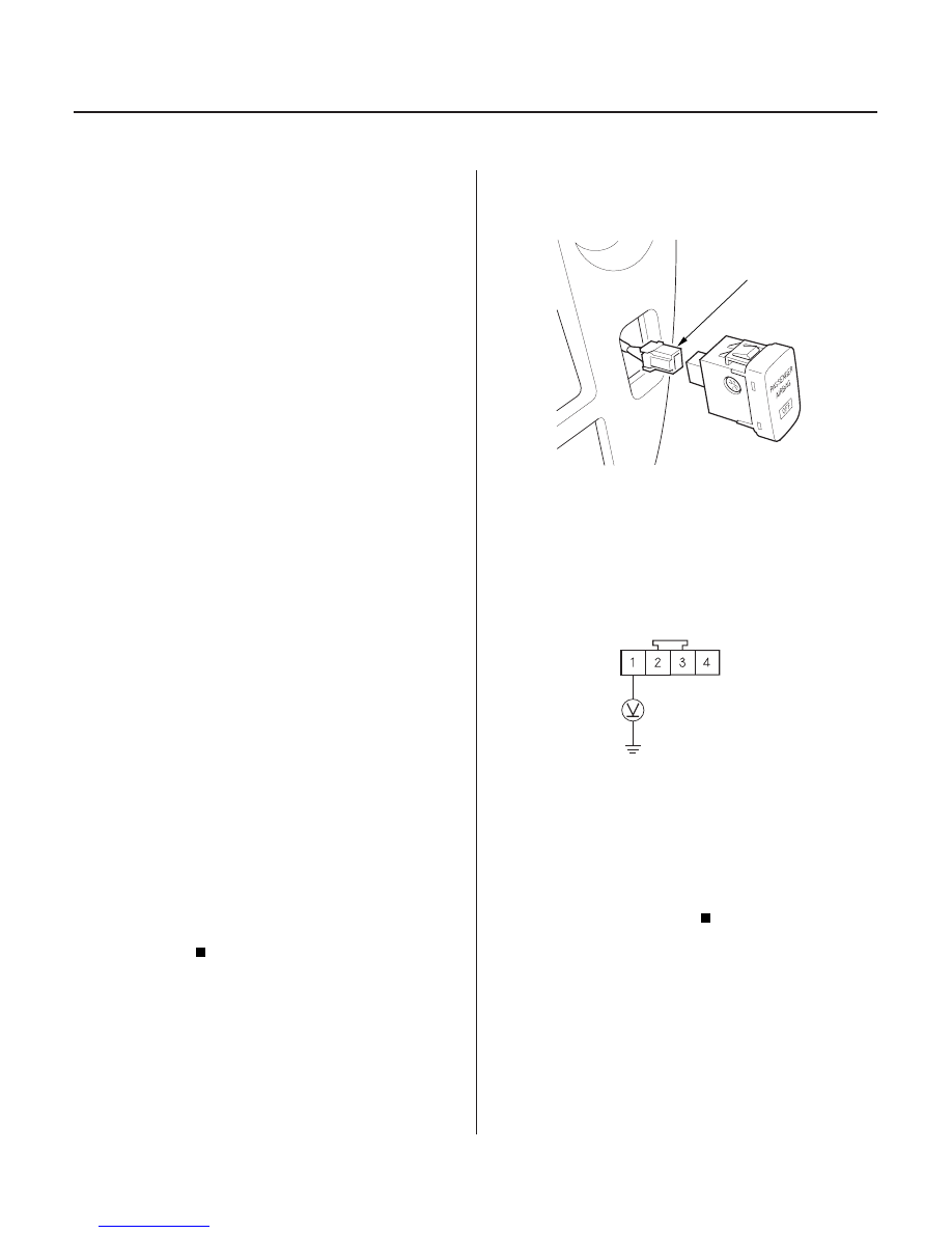
DASHBOARD WIRE HARNESS A 4P CONNECTOR
YEL
Open in Passenger Airbag Cutoff Indicator
1. Erase the DTC memory (see page 23-39).
2. Turn the ignition switch ON (II), and check that the
SRS indicator comes on for about 6 seconds and
then goes off.
Go to step 3.
Intermittent failure, system is OK at this time.
Go to Troubleshooting Intermittent Failures (see
page 23-39).
3. Check the connection between the dashboard wire
harness A 4P connector and the passenger’s airbag
cutoff indicator.
4. Erase the DTC memory.
5. Read the DTC (see page 23-38).
Go to step 6.
The system is OK; if DTC 92-1x is still present,
go to step 6.
6. Check the No. 9 (10A) fuse in the driver’s
under-dash fuse/relay box.
Go to step 7.
Replace the fuse, then turn the ignition switch
ON (II). If the fuse blows again, check for a short in
the No. 9 (10A) fuse circuit (dashboard wire
harness A).
7. Disconnect the dashboard wire harness A 4P
connector from the passenger’s airbag cutoff
indicator.
8. Turn the ignition switch ON (II).
9. Check for voltage between the No. 1 terminal of the
dashboard wire harness A 4P connector and body
ground. There should be battery voltage.
Go to step 10.
Open in dashboard wire harness A; replace
dashboard wire harness A.
10. Turn the ignition switch OFF. Disconnect the
battery negative cable, and wait for 3 minutes.
Wire side of female terminals
Does the passenger air bag cutof f indicator stay
on?
Is DT C 92-1x indicated?
Is the f use OK ?
Is ther e batter y voltage?
03/07/29 10:41:16 61S0X050_230_0326