Honda Odyssey 2004. Manual - part 592
−
−
−
−
−
−
*04
11
*05
13
YES
NO
YES
NO
23-310
SRS
DTC Troubleshooting (cont’d)
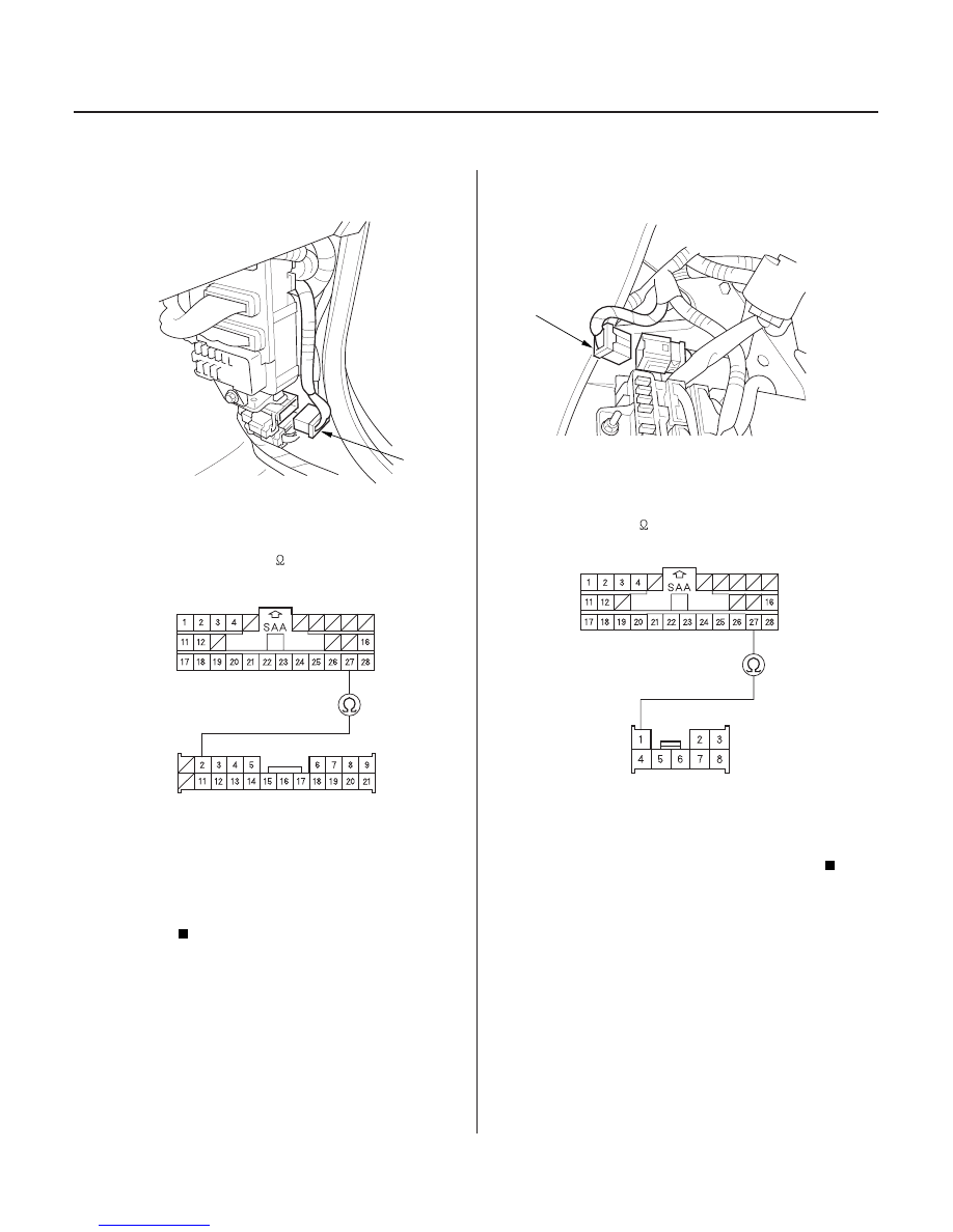
C505
SRS UNIT CONNECTOR B (28P)
BLU
BLU
C503
SRS UNIT CONNECTOR B (28P)
SRS MAIN HARNESS
8P CONNECTOR C503
BLU
BLU
25. Disconnect dashboard wire harness A 21P
connector C505 from the right side wire harness.
26. Check resistance between the No. 27 terminal of
SRS unit connector B (28P) and the No. 2 terminal
1.0
.
Open in the BLU wire of the right side wire
harness, passenger’s seat wire harness (with seat
heater), or OPDS unit harness; replace the faulty
harness.
Go to step 27.
27. Disconnect SRS main harness 8P connector C503
from dashboard wire harness A.
28. Check resistance between the No. 27 terminal of
SRS unit connector B (28P) and the No. 1 terminal
of SRS main harness 8P connector C503. There
should be 0
1.0
.
Open in the BLU wire of dashboard wire
harness A; replace dashboard wire harness A.
Go to step 29.
Wire side of female terminals
Wire side of female terminals
Is the r esistance as specif ied?
Is the r esistance as specif ied?
03/07/29 10:41:06 61S0X050_230_0310
of dashboard wire harness A 21P connector C505.
There should be 0
21P CONNECTOR C505
DASHBOARD WIRE HARNESS A