Honda Odyssey 2004. Manual - part 588


  Index      Honda     Honda Odyssey 2004 - service repair manual 2004 year


Search            


Content   ..  586  587  588  589   ..


Honda Odyssey 2004. Manual - part 588


05

06

07

YES

NO

YES

NO

23-294

SRS

DTC Troubleshooting (cont’d)

B

BLU

PASSENGER’S SEAT WIRE HARNESS 3P CONNECTOR
(WITH SEAT HEATER)
RIGHT SIDE WIRE HARNESS 3P CONNECTOR
(WITHOUT SEAT HEATER)

YEL/BLU

PASSENGER’S SEAT WIRE HARNESS 3P CONNECTOR
(WITH SEAT HEATER)
RIGHT SIDE WIRE HARNESS 3P CONNECTOR
(WITHOUT SEAT HEATER)

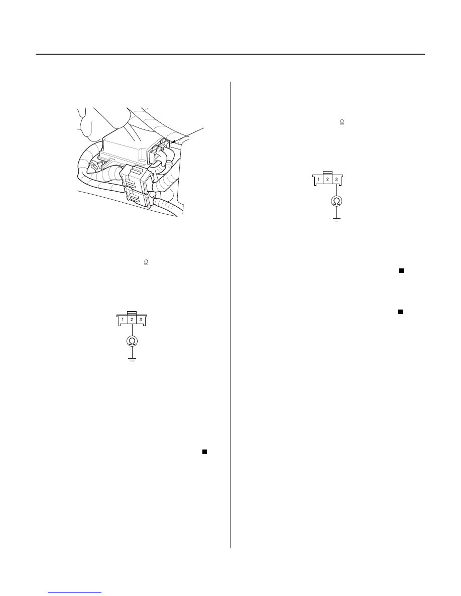
10. Disconnect SRS unit connector B (28P) from the

SRS unit.

11. Check resistance between the No. 2 terminal of the

passenger’s seat wire harness (with seat heater) or
right side wire harness (without seat heater) 3P
connector and body ground. There should be an
open circuit, or at least 1 M

.

Go to step 12.

Short to ground in the passenger’s seat wire

harness (with seat heater), right side wire harness,
dashboard wire harness A, SRS main harness or
SRS floor harness; replace the faulty harness.

12. Check resistance between the No. 3 terminal of the

passenger’s seat wire harness (with seat heater) or
right side wire harness (without seat heater) 3P
connector and body ground. There should be an
open circuit, or at least 1 M

.

Replace the SRS unit (see page 23-384).

Short to ground in the passenger’s seat wire

harness (with seat heater), right side wire harness,
dashboard wire harness A, SRS main harness or
SRS floor harness; replace the faulty harness.

Wire side of female terminals

Wire side of female terminals

Is the r esistance as specif ied?

Is the r esistance as specif ied?

03/07/29 10:39:53 61S0X050_230_0294

01

02

03

S0X4AZBK791000R711XFAAT20

’03-04 Models

DTC 71-1x (71-10 to 71-19, 71-1A to 71-1F):

YES

NO

YES

NO

23-295

A

A

A

Open in the Driver’s Seat Position Sensor

1. Erase the DTC memory (see page 23-39).

2. Turn the ignition switch ON (II), and check that the

SRS indicator comes on for about 6 seconds and
then goes off.

Go to step 3.

Intermittent failure, system is OK at this time.

Go to Troubleshooting Intermittent Failures (see
page 23-39).

3. Check the connection between the driver’s seat

wire harness 2P connector (with power seat) or
driver’s seat position sensor subharness 2P
connector (without power seat) and the driver’s
seat position sensor.

4. Erase the DTC memory.

5. Read the DTC (see page 23-38).

Go to step 6.

Repair the poor connections and retest. If DTC

71-1x is still present, go to step 6.

6. Turn the ignition switch OFF. Disconnect the

battery negative cable, and wait for 3 minutes.

7. Disconnect the driver’s airbag 4P connector (A)

from the cable reel.

8. Disconnect the driver’s seat wire harness 2P

connector (with power seat) or driver’s seat
position sensor subharness 2P connector (without
power seat) from the driver’s seat position sensor
(A).

9. Connect the special tool (jumper connector) to the

driver’s seat wire harness 2P connector (with
power seat) or driver’s seat position sensor
subharness 2P connector (without power seat).

10. Disconnect both seat belt tensioner 2P connectors

from the side wire harness 2P connectors (A).

(cont’d)

Does the SRS indicator stay on?

Is DT C 7 1-1x indicated?

03/07/29 10:39:54 61S0X050_230_0295

04

05

*01

07

YES

NO

YES

NO

23-296

SRS

DTC Troubleshooting (cont’d)

B

SRS UNIT CONNECTOR B (28P)

GRN/RED

GRN/YEL

C852

A

SRS FLOOR SUBHARNESS 28P CONNECTOR

GRN/YEL

GRN/RED

11. Disconnect SRS unit connector B (28P) from the

SRS unit.

12. Check resistance between the No. 16 and No. 28

terminals of SRS unit connector B (28P). There
should be 0

1.0

.

Faulty driver’s seat position sensor or SRS

unit; replace the driver’s seat position sensor (see
page 23-392). If the problem is still present, replace
the SRS unit (see page 23-384).

Go to step 13.

13. Disconnect SRS floor harness 28P connector (A)

from the SRS floor subharness connector C852.

14. Check resistance between the No. 9 and No. 10

terminals of SRS floor subharness 28P connector.
There should be 0

1.0

.

Open in the SRS floor harness; replace the

SRS floor harness.

Go to step 15.

Wire side of female terminals

Wire side of female terminals

Is the r esistance as specif ied?

Is the r esistance as specif ied?

03/07/29 10:39:55 61S0X050_230_0296

08

09

*02

YES

NO

YES

NO

23-297

LEFT SIDE WIRE HARNESS 3P CONNECTOR

GRN/YEL

GRN/RED

DRIVER’S SEAT WIRE HARNESS 12P CONNECTOR
(WITH POWER SEAT)

BLK

WHT

DRIVER’S SEAT POSITION SENSOR SUBHARNESS
2P CONNECTOR
(WITHOUT POWER SEAT)

WHT

BLK

15. Disconnect SRS floor subharness 3P connector

C558 from the left side wire harness.

16. Check resistance between the No. 2 and No. 3

terminals of left side wire harness 3P connector.
There should be 0

1.0

.

Open in the SRS floor subharness; replace

the SRS floor subharness.

Go to step 17.

17. Disconnect the left side wire harness 12P connector

C552 from the driver’s seat wire harness (with
power seat) or the left side wire harness 2P
connector C559 from the driver’s seat position
sensor subharness (without power seat).

18. Check resistance between the No. 5 and No. 12

terminals of the driver’s seat wire harness 12P
connector (with power seat) or between the No. 1
and No. 2 terminals of the driver’s seat position
sensor subharness 2P connector (without power
seat). There should be 0

1.0

.

Open in the left side wire harness; replace

the left side wire harness.

Open in the driver’s seat wire harness (with

power seat) or driver’s seat position sensor
subharness (without power seat); replace the faulty
harness.

Wire side of female terminals

Terminal side of male terminals

Terminal side of male terminals

Is the r esistance as specif ied?

Is the r esistance as specif ied?

03/07/29 10:39:55 61S0X050_230_0297


Content   ..  586  587  588  589   ..