Honda Odyssey 2004. Manual - part 565
−
−
−
−
01
01
S0X4AZBK791000R114XFAAT20
’03-04 Models
DTC 11-1x (11-10 to 11-19, 11-1A to 11-1F):
DTC 11-4x (11-40 to 11-49, 11-4A to 11-4F):
Special Tools Required
YES
NO
YES
NO
23-202
SRS
DTC Troubleshooting (cont’d)
A
07XAZ-SZ30100
07SAZ-TB4011A
A
Open or Increased Resistance in Driver’s
Airbag First Inflator
Open or Increased Resistance in Driver’s
Airbag Second Inflator
• SRS inflator simulator 07SAZ-TB4011A
• SRS simulator lead F 07XAZ-SZ30100
1. Erase the DTC memory (see page 23-39).
2. Turn the ignition switch ON (II), and check that the
SRS indicator comes on for about 6 seconds and
then goes off.
Go to step 3.
Intermittent failure, system is OK at this time.
Go to Troubleshooting Intermittent Failures (see
page 23-39).
3. Turn the ignition switch OFF. Disconnect the
battery negative cable, and wait for 3 minutes.
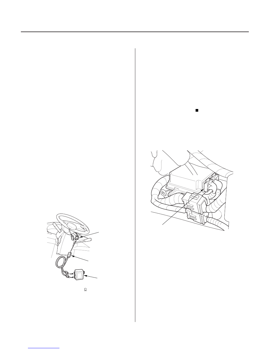
4. Disconnect the driver’s airbag 4P connector from
the cable reel (A).
5. Connect the special tool (2
connectors) to the
cable reel 4P connector.
6. Reconnect the battery negative cable.
7. Erase the DTC memory.
8. Read the DTC (see page 23-38).
Go to step 9.
Open or increased resistance in the driver’s
airbag first or second inflator; replace the driver’s
airbag (see page 23-368).
9. Turn the ignition switch OFF. Disconnect the
battery negative cable, and wait for 3 minutes.
10. Disconnect SRS unit connector A (28P) from the
SRS unit. Do not disconnect the special tool from
the cable reel 4P connector.
11. Disconnect the SRS inflator simulator from SRS
simulator lead F.
Does the SRS indicator stay on?
Is DT C 11-1x or 11-4x indicated?
03/07/29 10:37:44 61S0X050_230_0202