Honda Odyssey 2004. Manual - part 562
−
−
−
−
−
*02
04
05
YES
NO
YES
NO
23-190
SRS
DTC Troubleshooting (cont’d)
D
A
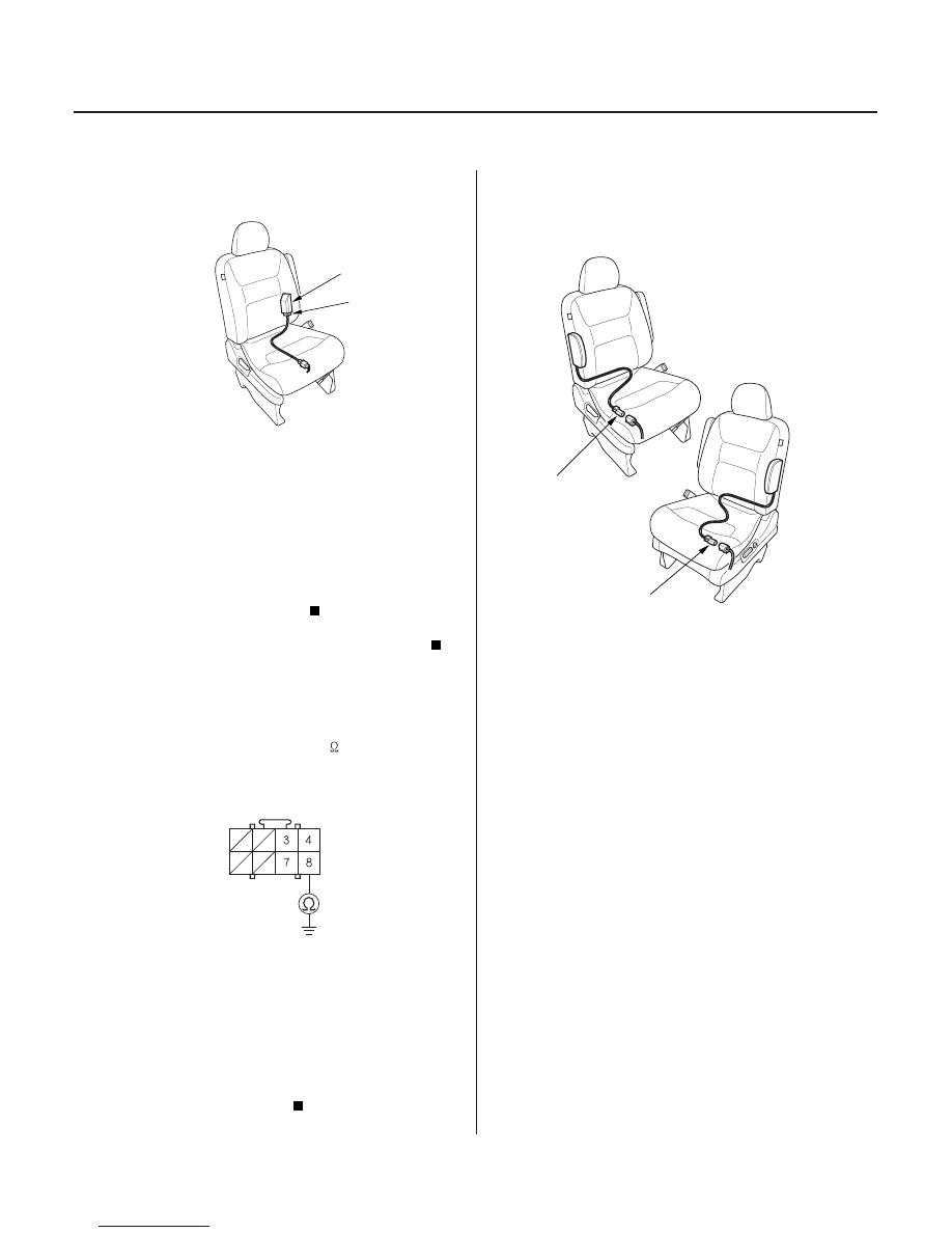
OPDS UNIT HARNESS CONNECTOR D (8P)
A
A
13. Disconnect OPDS unit harness connector D (8P)
from the OPDS unit (A).
14. Turn the ignition switch ON (II) for 30 seconds, then
turn it off.
15. Check the No. 11 (10A) fuse in the under-dash
fuse/relay box.
Short to ground in the OPDS unit; replace the
OPDS unit (see page 23-387).
Short to ground in the No. 11 (10A) circuit.
16. Turn the ignition switch OFF.
17. Check resistance between the No. 8 terminal of
OPDS unit harness connector D (8P) and body
ground. There should be 0
1.0
.
Go to step 18.
Open in the right side wire harness or OPDS
unit harness, or poor ground (G581). If G581 is OK,
replace the faulty harness.
18. Turn the ignition switch OFF. Disconnect the
battery negative cable, and wait for 3 minutes.
19. Disconnect both side airbag connectors (A).
Wire side of female terminals
Is the f use OK ?
Is the r esistance as specif ied?
03/07/29 10:36:31 61S0X050_230_0190