Honda Odyssey 2004. Manual - part 544
−
−
−
−
04
05
*01
07
YES
NO
YES
NO
23-118
SRS
DTC Troubleshooting (cont’d)
A
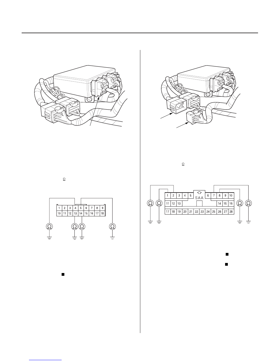
SRS UNIT CONNECTOR A (18P)
C851
A
SRS MAIN HARNESS 28P CONNECTOR
12. Disconnect SRS unit connector A (18P) from the
SRS unit.
13. Disconnect the special tool from the SRS main
harness 4P connector.
14. Check resistance between the No. 4 terminal of
SRS unit connector A (18P) and body ground, and
the No. 13 terminal and body ground, the No. 5
terminal and body ground, and the No. 14 terminal
and body ground. There should be an open circuit,
or at least 1 M
.
Faulty SRS unit; replace the SRS unit (see
page 23-382).
Go to step 15.
15. Disconnect the SRS main harness 28P connector
(A) from the SRS floor harness 28P connector C851.
16. Check resistance between the No. 7 terminal of the
SRS main harness 28P connector and body ground,
the No. 8 terminal and body ground, the No. 1
terminal and body ground, and the No. 2 terminal
and body ground. There should be an open circuit,
or at least 1 M
.
Replace the SRS floor harness.
Replace the SRS main harness.
Wire side of female terminals
Wire side of female terminals
Is the r esistance as specif ied?
Is the r esistance as specif ied?
03/07/29 10:34:37 61S0X050_230_0118