Honda Odyssey 2004. Manual - part 532
−
−
−
−
−
−
01
02
S0X4AZ4K79100081013FAAT00
’99-01 Models
DTC 1-3:
YES
NO
YES
NO
YES
NO
23-70
SRS
DTC Troubleshooting (cont’d)
A
07TAZ-SZ5011A
07SAZ-TB4011A
A
07TAZ-SZ5011A
07SAZ-TB4011A
Short to Another Wire or Decreased
Resistance in Driver’s Airbag Inflator
1. Erase the DTC memory (see page 23-38).
2. Turn the ignition switch ON (II), and check that the
SRS indicator comes on for about 6 seconds and
then goes off.
Go to step 3.
Intermittent failure, system is OK at this time.
Go to Troubleshooting Intermittent Failures (see
page 23-39).
3. Turn the ignition switch OFF. Disconnect the
battery negative cable, and wait for 3 minutes.
4. Disconnect the driver’s airbag 2P connector from
the cable reel 2P connector (A).
5. Connect the special tool (2
connector) to the
cable reel 2P connector.
6. Reconnect the battery negative cable.
7. Erase the DTC memory.
8. Read the DTC (see page 23-35).
Go to step 9.
Short in the driver’s airbag inflator; replace
the driver’s airbag (see page 23-368).
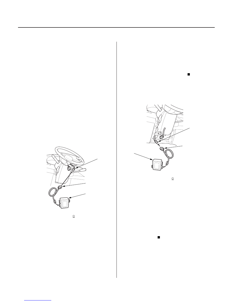
9. Turn the ignition switch OFF. Disconnect the
battery negative cable, and wait for 3 minutes.
10. Disconnect the cable reel 2P connector from the
SRS main harness 2P connector (A).
11. Connect the special tool (2
connector) to the SRS
main harness 2P connector.
12. Reconnect the battery negative cable.
13. Erase the DTC memory.
14. Read the DTC.
Go to step 15.
Short in the cable reel; replace the cable reel
(see page 23-376).
Does the SRS indicator stay on?
Is DT C 1-3 indicated?
Is DT C 1-3 indicated?
03/07/29 10:32:56 61S0X050_230_0070