Honda Odyssey 2004. Manual - part 496


  Index      Honda     Honda Odyssey 2004 - service repair manual 2004 year


Search            


Content   ..  494  495  496  497   ..


Honda Odyssey 2004. Manual - part 496


01

02

03

S0X4A00J16160746951FEAT00
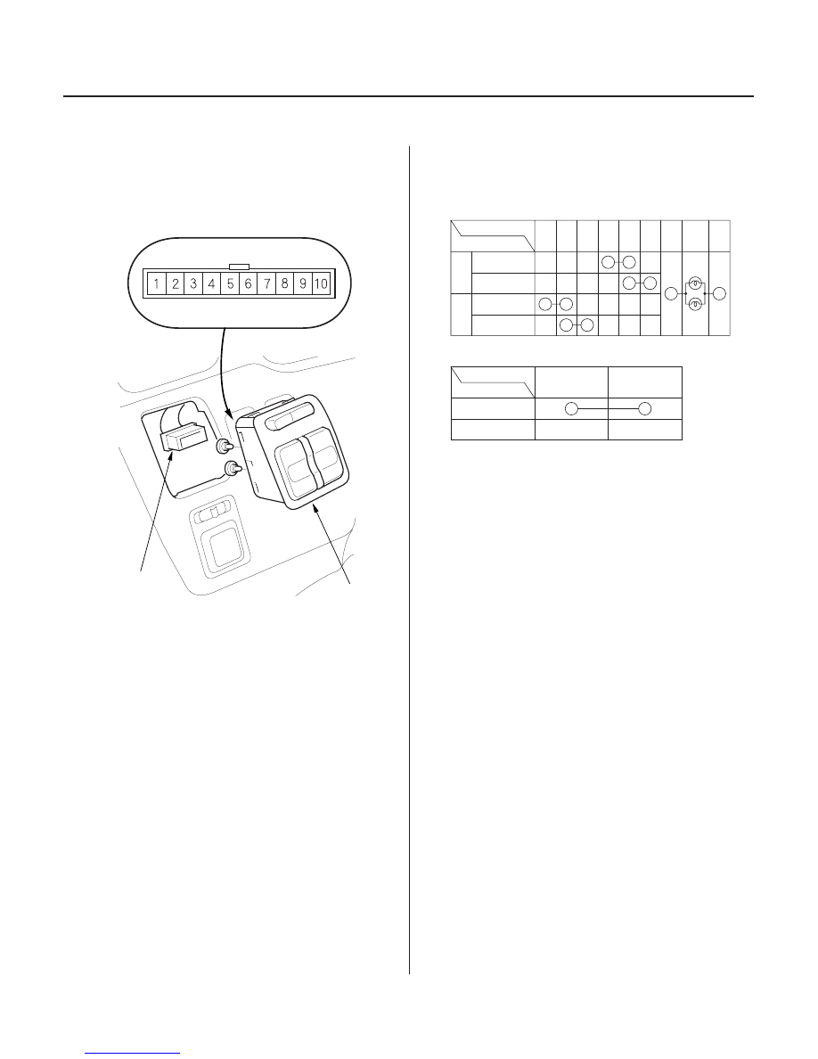
Open/Close Switch:

Main Switch:

22-312

Power Sliding Doors

Power Sliding Door Switch Test

B

A

Terminal

Position

2

3

4

8

9

5

6

L.

R.

OPEN

CLOSE

OPEN

CLOSE

7

Terminal

Position

ON

OFF

1

10

1.

2. Disconnect the 10P connector (A) from the power

sliding door switch (B).

3. Check for continuity between the terminals in each

switch position according to the table.

4. If the continuity is not as specified, replace the

bulbs (C) or the switch.

03/07/29 10:27:19 61S0X050_220_0314

20-69).

Remove the dashboard lower cover (see page

*01

02

S0X4A00J16160755665FEAT00

Body Side (’99-00 EX models)

22-313

Sliding Door Junction Switch Test

Right:

F

E

D

C

B

A

J

I

H

G

G

H

I

J

A

B

C

D

E

F

Left:

A

B

1

2

3

4

5

A

B

C

D

G

6

7

8

9

10

E

F

H

I

J

1. Remove the center pillar trim (see page 20-58).

2. Disconnect the 10P connector (A) from the switch

(B).

3. Check for continuity between the terminals

according to the tables.

4. If the continuity is not as specified, replace the

switch.

(cont’d)

Terminal side of
male terminals

03/07/29 10:27:20 61S0X050_220_0315

02

02

Body Side (’01-04 EX and ’02-04 EXL models)

22-314

Power Sliding Doors

Sliding Door Junction Switch Test (cont’d)

Right:

Left:

B

A

A

B

C

D

E

F

G

H

I

J

K

K

J

I

H

F

E

D

C

B

A

G

7

8

9

10

11 12

E

F

H

I

J

K

1

2

3

4

6

A

B

C

D

G

1. Remove the sliding door panel (see page 20-13).

2. Disconnect the 12P connector (A) from the switch

(B).

3. Check for continuity between the terminals

according to the tables.

4. If the continuity is not as specified, replace the

switch.

Terminal side of
male terminals

03/07/29 10:27:20 61S0X050_220_0316

*02

06

Door Side (’99-00 EX models)

22-315

YEL/
RED

BLK

WHT/
RED

Right:

Left:

BLU/
BLK

LT GRN/
RED

BLK

GRN/
BLK

GRN/
RED

BLK

YEL/
GRN

BLU/
YEL

WHT/
RED

BLU/
RED

BLK

Left:

YEL/
RED

WHT/
RED

Right:

A

B

C

D

E

F

G

H

I

J

F

D

C

B

A

J

I

H

G

BLU/
RED

BLU/
WHT

E

RED/
WHT

BLU/
WHT

A

A

B

C

D

E

F

G

B1 B3 B4

H

I

J

K A3, A5, A6, D1, A4 A8

B6

D2

C2

D4

C3 C4

E2 D1, B5, E3

E1 C1,

D3

1. Remove the sliding door panel (see page 20-13).

2. Disconnect the connectors from the switch (A).

3. Check for continuity between the terminals

according to the tables.

4. If the continuity is not as specified, replace the

switch.

(cont’d)

Wire side of female terminals

Terminal side of
male terminals

Wire side of
female terminals

03/07/29 10:27:21 61S0X050_220_0317


Content   ..  494  495  496  497   ..