Honda Odyssey 2004. Manual - part 475


  Index      Honda     Honda Odyssey 2004 - service repair manual 2004 year


Search            


Content   ..  473  474  475  476   ..


Honda Odyssey 2004. Manual - part 475


02

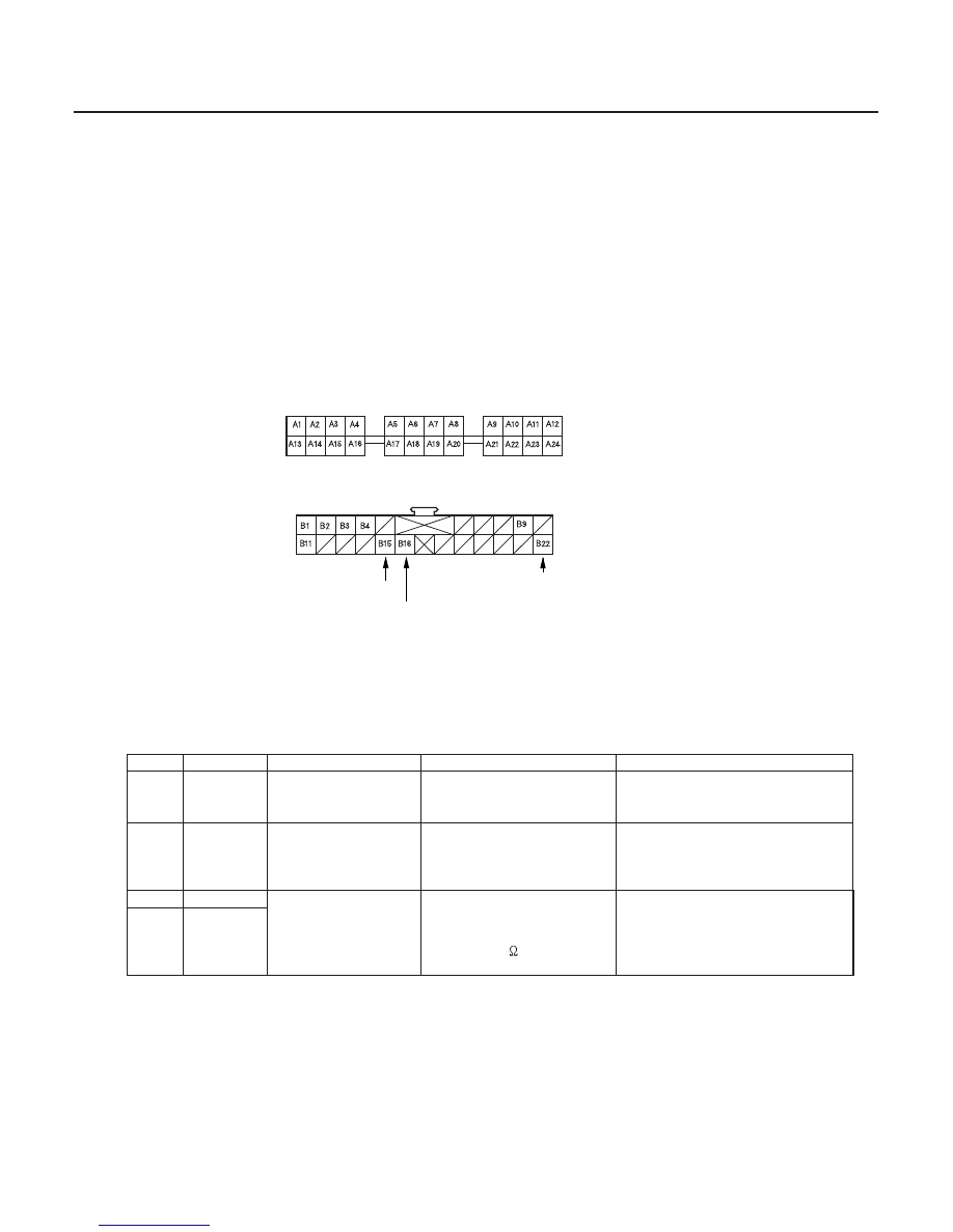
Passenger’s Multiplex Control Unit

Cavity

Wire

Test condition

Test: Desired result

Possible cause if result is not obtained

22-228

Wipers/Washers

Control Unit Input Test (cont’d)

GRN/WHT

BLK

GRN/YEL

PASSENGER’S MULTIPLEX CONTROL UNIT CONNECTOR B

PASSENGER’S UNDER-DASH FUSE/RELAY BOX SOCKET
(Passenger’s multiplex control unit connector A)

5. Remove the passenger’s under-dash fuse/relay box (see page 22-86).

6. Remove the passenger’s multiplex control unit from the passenger’s under-dash fuse/relay box, and disconnect

its connector.

7. Inspect all connector and socket terminals to be sure they are making good contact.

• If the terminals are bent, loose or corroded, repair them as necessary, and recheck the system.
• If the terminals look OK, go to step 8.

8. With the passenger’s multiplex control unit still disconnected, make these input tests at the connector and the

fuse/relay box socket.

• If any test indicates a problem, find and correct the cause, then recheck the system.
• If all the input tests prove OK, the control unit must be faulty; replace it.


B22

BLK

Under all conditions

Check for continuity to
ground:
There should be continuity.

Poor ground (G503)
An open in the wire

A22

Fuse/relay

box socket

Ignition switch ON
(II)

Check for voltage to
ground:
There should be battery
voltage.

Blown No. 9 (10A) fuse in the
driver’s under-dash fuse/relay
box
An open in the wire

B15

GRN/WHT

Intermittent dwell
time control ring
turned

Check for resistance
between the terminals:
It should vary from 0 to
approx. 30 k

as the ring is

turned.

Faulty intermittent dwell time
controller
An open in the wire

B16

GRN/YEL

Wire side of female terminals

03/07/29 10:24:23 61S0X050_220_0230

11

13

S0X4A00J54300065721FEAT10

Windshield

Rear Window

22-229

Wiper Motor Test

B

A

B

A

1. Open the hood, and carefully remove the cap nuts

and the wiper arms. Make sure they do not touch
the hood.

2. Remove the hood seal and cowl cover.

3. Disconnect the 5P connector (A) from the motor (B).

4. Test the motor by connecting battery power to the

No. 4 terminal and ground to the No. 2 terminal of
the wiper motor 5P connector. The motor should
run at low speed. If the motor does not run or fails
to run smoothly, replace the motor.

5. Connect an analog voltmeter between the No. 5 (

)

and No. 3 (

) terminals, and run the motor at low

or high speed. The voltmater should indicate 12 V
and 4 V or less alternately.

6. If the motor test is not as specified, replace the

windshield wiper motor.

1. Open the tailgate, and remove the tailgate lower

panel (see page 20-61).

2. Disconnect the 4P connector (A) from the motor (B).

3. Test the motor by connecting battery power to the

No. 1 terminal and ground, to the No. 3 terminal of
the 4P connector. The motor should run. If the
motor does not run or fails to run smoothly, replace
the motor.

4. Test the wiper motor park switch by connecting an

analog voltmeter between the No. 4 (

) terminal

and ground, and run the motor. The voltmeter
should indicate 12 V and 4 V or less alternately.

5. If the motor test is not as specified, replace the rear

window wiper motor.

03/07/29 10:24:23 61S0X050_220_0231

11

S0X4A00J54300065021FEAT01

11

S0X4A04J54300065011FEAT02

Canada

22-230

22-230

Wipers/Washers

Washer Motor Test

Washer Fluid Level Switch Test

A

B

A

B

1. Remove the right inner fender (see page 20-149).

2. Disconnect the 2P connectors (A) from the washer

motors (B).

3. Test the motor by connecting battery power to the

No. 1 terminal and ground the No. 2 terminal of the
washer motor. The motor should run.

• If the motor does not run or fails to run smoothly,

replace it.

• If the motor runs smoothly, but little or no

washer fluid is pumped, check for a disconnected
or blocked washer hose, or a clogged pump
outlet in the motor.

1. Remove the right inner fender (see page 20-149).

2. Disconnect the 2P connector (A) from the washer

level switch.

3. Remove the washer fluid level switch from the

washer reservoir.

NOTE: Fluid may flow out of the opening.

4. Check for continuity between the No. 1 and No. 2

terminals in each float position (B).

• There should be continuity when the float is

down.

• There should be no continuity when the float is

up.

5. If the continuity is not as specified, replace the

switch.

03/07/29 10:24:24 61S0X050_220_0232

11

12

*01

S0X4A00J54300065721KBAT10

22-231

Windshield Wiper Motor Replacement

B

A
24.5 N·m
(2.5 kgf·m, 18 lbf·ft)

C
9.8 N·m (1.0 kgf·m, 7.2 lbf·ft)

D

B

A

E

B

C

31 N·m (3.2 kgf·m,
23 lbf·ft)

8 N·m (0.8 kgf·m,
6.0 lbf·ft)

A

1. Open the hood. Remove the nuts (A) and the

windshield wiper arms (B).

2. Remove the hood seal and cowl cover.

3. Disconnect the 5P connector (A) from the wiper

motor (B).

4. Remove the bolts (C), move windshield wiper

linkage assembly (D) toward the passenger’s side
of the vehicle until it slides off of the pin (E), then
remove the assembly.

5. Scribe a line (A) across the link and windshield

wiper linkage to show the original adjustment.
Separate the windshield wiper linkage (B) from the
wiper motor (C).

6. Install in the reverse order of removal, and note

these items:

• Grease the moving parts.
• Before reinstalling the wiper arms, turn the wiper

switch ON, then OFF to return the wiper shafts to
the park position.

• If necessary, replace any damaged clips.
• Check the wiper motor operation.

Remove and
replace the clips

03/07/29 10:24:25 61S0X050_220_0233


Content   ..  473  474  475  476   ..