Honda Odyssey 2004. Manual - part 468
01
S0X4AZBJ54460600000CAAT00
’03-04 models
Resetting the power window control unit is required after performing the following procedures
22-200
Power Windows
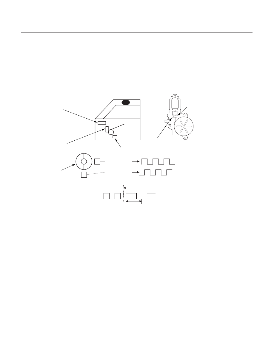
HALL IC UNIT
MAGNET
POWER WINDOW
CONTROL UNIT
POWER WINDOW MOTOR
SWITCH
Sensor
MAGNET
IC
IC
N
S
Period of pulses
Period of pulses
Period of
pulses
Position when something
is pinched
Threshold value for
judgement of pinching
The driver’s window will stop and automatically open if you pinch your hand or something during auto-up operation.
The system is composed of the power window master switch, the power window control unit and the driver’s window
motor.
The power window motor incorporates a pulser which generates pulses during the motor’s operation and sends the
pulses to the power window control unit. As soon as the power window control unit detects no pulses from the pulser,
the control unit makes the power window motor stop and reverse.
• Disconnecting the battery.
• Removing the No. 79 (20A) fuse in the under-hood subfuse box.
• Disconnecting the 18P connector from the power window control unit.
• Removing the window regulator, glass or glass run channel.
• Disconnecting the driver’s door wire harness.
1. Turn the ignition switch off, then back ON (II).
2. Move the driver’s window all the way down by holding the driver’s switch to the AUTO DOWN position; when the
window reaches the bottom, hold the driver’s window switch in the AUTO DOWN position for 2 seconds.
3. Move the driver’s window all the way up without stopping by holding the driver’s switch to the AUTO UP position;
when the window reaches the top, hold the driver’s window switch in the AUTO UP position for 2 seconds.
If the window does not work in AUTO, reset the power window control unit according to the above procedures again.
03/07/29 10:24:07 61S0X050_220_0202
System Description
Resetting the Power Window Control Unit
POWER WINDOW MASTER
'03-04 models