Honda Odyssey 2004. Manual - part 460
*01
S0X4A00G24166150451FEAT01
*01
*02
S0X4A00G24166150451LBAT02
22-168
22-168
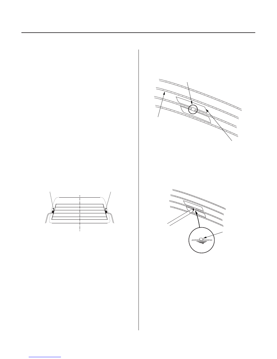
Rear Window Defogger
Function Test
Defogger Wire Repair
A
B
C
B
A
A
NOTE: Be careful not to scratch or damage the defogger
wires with the tester probe.
1. Check for voltage between the positive terminal
(Passenger’s side) (A) and body ground with the
ignition switch and defogger switch ON.
There should be battery voltage.
• If there is no voltage,
– Check for voltage at the WHT/GRN wire at the
rear window defogger relay. If there is no
voltage at the WHT/GRN wire, check for a
blown fuse No. 53 (30A) in the under-hood
fuse/relay box or an open in the wire.
– With the ignition switch ON (II), check for
voltage at the BLK/YEL wire of the rear window
defogger relay. If there is no voltage at the
BLK/YEL wire, check for a blown No. 3 (7.5A)
fuse in the driver’s under-dash fuse/relay box
or an open in the wire.
– With the ignition switch ON (II), and the rear
window defogger relay installed, jump to
ground BRN/YEL wire at the climate control
unit (heater control panel). There should be
voltage at the BLK/GRN wire. If there is no
voltage at the BLK/GRN wire, check for an open
in the BLK/GRN wire or a faulty rear window
defogger relay.
• If there is battery voltage, go to step 2.
2. Check for continuity between the negative terminal
(Driver’s side) (B) and body ground. If there is no
continuity, check for an open in the defogger
ground wire.
3. Touch the voltmeter positive probe to the halfway
point of each defogger wire, and the negative
probe to the negative terminal. There should be
approximately 6 V with the ignition switch and the
defogger switch ON.
• If the voltage is as specified, the defogger wire is
OK.
• If the voltage is not as specified, repair the
defogger wire.
– If it is more than 6 V, there is a break in the
negative half of the wire.
– If it is less than 6 V, there is a break in the
positive half of the wire.
NOTE: To make an effective repair, the broken section
must be no longer than one inch.
1. Lightly rub the area around the broken section (A)
with fine steel wool, then clean it with alcohol.
2. Carefully mask above and below the broken portion
of the defogger wire (B) with cellophane tape (C).
3. Mix the silver conductive paint thoroughly. Using a
small brush, apply a heavy coat of paint extending
about 1/8’’ on both sides of the break. Allow 25
minutes to dry.
4. Check for continuity in the repaired wire.
5. Apply a second coat of paint in the same way. Let it
dry 3 hours before removing the tape.
03/07/29 10:22:39 61S0X050_220_0170