Honda Odyssey 2004. Manual - part 450
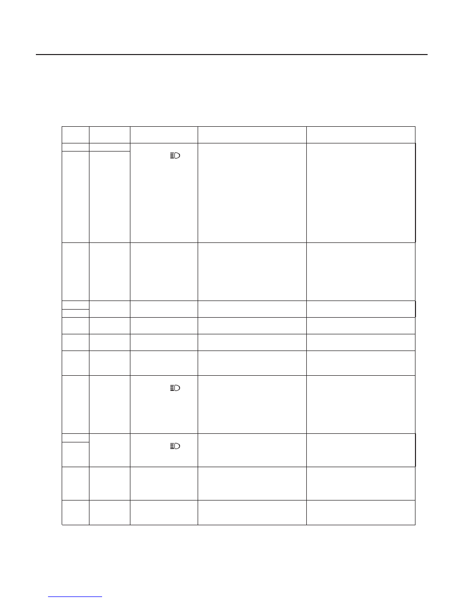
Cavity
Wire
Test condition
Test: Desired result
Possible cause if result is not
obtained
22-128
Exterior Lights
Daytime Running Lights Control Unit Input Test (cont’d)
4. Make these input tests at the connector.
• If any test indicates a problem, find and correct the cause, then recheck the system.
• If all the input tests prove OK, the control unit must be faulty; replace it.
•
•
•
•
•
•
•
•
•
•
•
•
•
•
•
•
•
•
•
•
•
•
•
•
•
•
•
•
•
1
RED/ORN
Combination light
switch ON (
),
and dimmer switch
in HIGH
Connect a jumper wire between
No. 1 and No. 2 terminals and
connect No. 11 terminal to
ground:
The headlights (HIGH) and high
beam indicator light should
come on.
Blown No. 55 (40A) fuse in
the under-hood fuse/relay
box
Blown No. 6 (10A) fuse in the
passenger’s under-dash fuse/
relay box
Blown headlight bulb (High
beam)
Blown high beam indicator
light
An open in the wire
Poor ground (G401)
11
RED/WHT
2
RED/BLU
Under all
conditions
Check for voltage to ground:
There should be battery voltage.
Blown No. 55 (40A) fuse in
the under-hood fuse/relay
box
Blown No. 6 (10A) fuse in the
passenger’s under-dash fuse/
relay box
An open in the wire
4
BLK
Under all
conditions
Check for continuity to ground:
There should be continuity.
Poor ground (G401)
An open in the wire
7
6
GRN/WHT
Parking brake
pedal pressed
Check for continuity to ground:
There should be continuity.
Faulty parking brake switch
An open in the wire
8
BLU/RED
Headlights OFF
Check for voltage to ground:
There should be battery voltage.
Faulty headlight relay 1
An open in the wire
9
BLU/WHT
Ignition switch ON
(II)
Connect to ground:
The indicator light should come
on.
Faulty DRL indicator light
An open in the wire
10
RED/YEL
Combination light
switch ON (
),
and dimmer switch
in HIGH
Check for voltage to ground:
There should be battery voltage.
Blown No. 45 (15A) fuse in
the under-hood fuse/relay
box
Faulty combination light
switch
Faulty headlight relay 2
An open in the wire
3
ORN/WHT
Combination light
switch ON (
)
Check for continuity to ground:
There should be continuity.
Faulty combination light
switch
Poor ground (G401)
An open in the wire
5
12
YEL/RED
Ignition switch ON
(II)
Check for voltage to ground:
There should be battery voltage.
Blown No. 5 (7.5A) fuse in the
driver’s under-dash fuse/relay
box
An open in the wire
13
GRN/RED
Brake fluid
reservoir float in
down position
Check for continuity to ground:
There should be continuity.
Faulty brake fluid level switch
An open in the wire
Poor ground (G302)
03/07/29 10:21:22 61S0X050_220_0130