Honda Odyssey 2004. Manual - part 423


  Index      Honda     Honda Odyssey 2004 - service repair manual 2004 year


Search            


Content   ..  421  422  423  424   ..


Honda Odyssey 2004. Manual - part 423


Engine Wire Harness (’99-01 models) (cont’d)

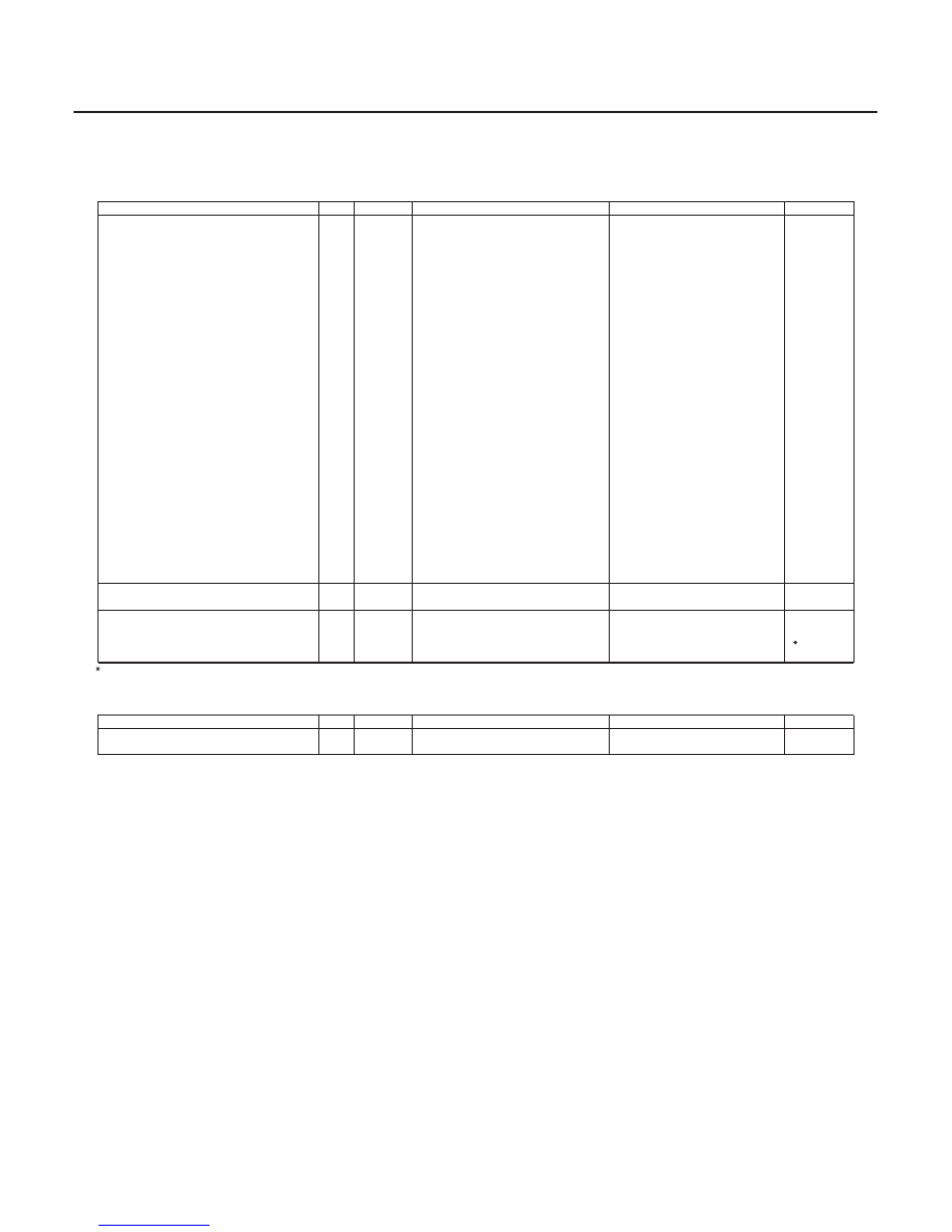
Knock Sensor Subharness

Connector or Terminal

Ref

Cavities

Location

Connects to

Notes

Connector or Terminal

Ref

Cavities

Location

Connects to

Notes

22-20

Connectors and Harnesses

Connector to Harness Index (cont’d)

Primary heated oxygen sensor
(PHO2S)

15

4

Left side of engine compartment

Radiator fan switch A

26

2

Left side of engine compartment

Radiator fan switch B

52

2

Right side of engine compartment

Second clutch pressure switch

35

1

On transmission housing

Shift solenoid valve B

36

2

On transmission housing

Shift solenoid valve C

37

2

On transmission housing

Starter solenoid

34

1

Left side of engine compartment

TDC sensor 1 and 2

51

4

Right side of engine compartment

Third clutch pressure switch

33

1

On transmission housing

Throttle position (TP) sensor

38

3

Left side of engine compartment

Torque converter clutch solenoid valve
and shift solenoid valve A

24

3

On transmission housing

Transmission range switch

19

10

On transmission housing

Vehicle speed sensor (VSS)

17

3

Left side of engine compartment

VTEC pressure switch

54

2

Right side of engine compartment

VTEC solenoid valve

56

1

Right side of engine compartment

C101

27

10

Left side of engine compartment

Left engine compartment wire
harness (see page 22-28)

C102

28

14

Left side of engine compartment

Left engine compartment wire
harness (see page 22-28)

C103

3

1

Right side of engine compartment

Knock sensor subharness

C104 (Junction connector)

23

8

Left side of engine compartment

C105 (Junction connector)

20

14

Left side of engine compartment

C106 (Junction connector)

16

20

Under middle of dash

C107 (Junction connector)

13

20

Under middle of dash

C108

29

1

Left side of engine compartment

Left engine compartment wire
harness (see page 22-28)

T101

1

Under-hood fuse/relay box

T102

49

Alternator

G101

21

Left side of engine compartment

Engine ground via engine
wire harness

G102

2

Right side of engine compartment

Engine ground via engine
wire harness

3

3: ’00-01 models

Knock sensor

50

1

Middle of engine compartment

C103

3

1

Middle of engine compartment

Engine wire harness

Navigation

Navigation

03/07/29 10:17:58 61S0X050_220_0022

02

22-21

ENGINE WIRE
HARNESS

20

19

18

17

16

15

14

13

12

11

10

9

8

7

6

5

4

3

1

22

23

24

25

26

27

28

29

30

31

32

33

34

35

36

37

38

39

40

41

42

43

44

45

46

47

48

49

50

51

52

53

54

55

56

KNOCK SENSOR
SUBHARNESS

2

21

03/07/29 10:17:58 61S0X050_220_0023

S0X4AZAJ54283225101DBAT10

Engine Wire Harness (’02-04 models)

Connector or Terminal

Ref

Cavities

Location

Connects to

Notes

22-22

Connectors and Harnesses

Connector to Harness Index (cont’d)

Alternator

47

4

Middle of engine compartment

A/T clutch pressure control valve A

28

2

Left side of engine compartment

A/T clutch pressure control valve B

27

2

Left side of engine compartment

A/T clutch pressure control valve C

32

2

Left side of engine compartment

CKP sensor

54

2

Right side of engine compartment

CMP sensor A and B

50

4

Right side of engine compartment

EGR valve and EGR valve lift sensor

39

6

Left side of engine compartment

Engine coolant temperature (ECT)
sensor

40

2

Middle of engine compartment

Engine oil pressure switch

52

1

Right side of engine compartment

EVAP canister purge valve

37

2

Middle of engine compartment

4th clutch pressure switch

30

1

Transmission housing

Idle air control (IAC) valve

20

3

Left side of engine compartment

Ignition coil No. 1

5

3

Middle of engine compartment

Ignition coil No. 2

7

3

Middle of engine compartment

Ignition coil No. 3

9

3

Middle of engine compartment

Ignition coil No. 4

46

3

Middle of engine compartment

Ignition coil No. 5

43

3

Middle of engine compartment

Ignition coil No. 6

41

3

Middle of engine compartment

Injector No. 1

4

2

Middle of engine compartment

Injector No. 2

6

2

Middle of engine compartment

Injector No. 3

8

2

Middle of engine compartment

Injector No. 4

45

2

Middle of engine compartment

Injector No. 5

44

2

Middle of engine compartment

Injector No. 6

42

2

Middle of engine compartment

Input shaft (Mainshaft) speed sensor

29

3

On transmission housing

Intake air temperature (IAT) sensor

14

2

Middle of engine compartment

MAP sensor

17

3

Left side of engine compartment

Output shaft (Countershaft) speed
sensor

22

3

On transmission housing

PCM connector B

10

25

Under middle of dash

PCM connector C

11

31

Under middle of dash

PCM connector D

12

16

Under middle of dash

03/07/29 10:17:58 61S0X050_220_0024

01

22-23

20

19

18

17

16

15

14

13

12

11

10

9

8

7

6

5

4

3

1

22

23

24

25

26

27

28

29

30

31

32

33

34

35

36

37

38

39

40

41

42

43

44

45

46

47

48

49

50

51

52

53

54

55

KNOCK SENSOR
SUBHARNESS

2

21

ENGINE WIRE
HARNESS

(cont’d)

03/07/29 10:17:59 61S0X050_220_0025


Content   ..  421  422  423  424   ..