Honda Odyssey 2004. Manual - part 411


  Index      Honda     Honda Odyssey 2004 - service repair manual 2004 year


Search            


Content   ..  409  410  411  412   ..


Honda Odyssey 2004. Manual - part 411


01

02

S0X4A10G24113614631FEAT00

01

S0X4A81G10500016711KDAT11

Without Navigation System

21-120

21-120

Climate Control

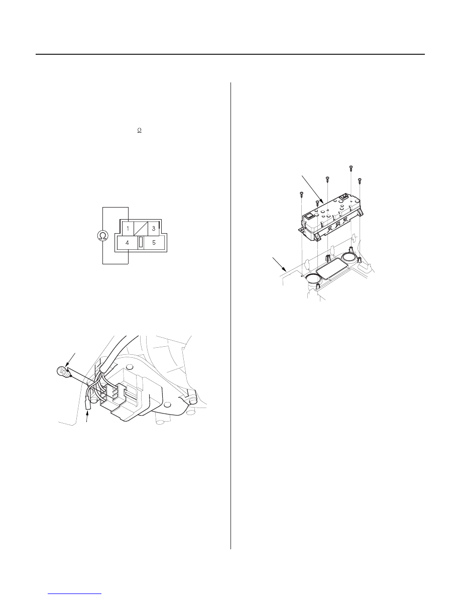
Power Transistor Test

Climate Control Unit Removal and
Installation

POWER TRANSISTOR

A

B

B

A

1. Disconnect the 5P connector from the power

transistor.

2. Measure the resistance between the No. 1 and

No. 4 terminals of the power transistor. It should be
approximately 1.4

1.5 k

.

• If the resistance is within the specifications, go to

step 3.

• If the resistance is not within the specifications,

replace the power transistor.

3. Carefully release the lock tab on the No. 3 terminal

(ORN/BLK) (A) in the 5P connector, then remove the
terminal and insulate it from body ground.

4. Connect a 1.2

3.4 W bulb (B) between the No. 3

and the No. 4 cavity on the 5P connector.

5. Reconnect the 5P connector to the power transistor.

6. Turn the ignition switch ON (II), and check that the

blower motor runs.

• If the blower motor does not run, replace the

power transistor.

• If the blower motor runs, replace the climate

control unit.

1. Remove the center panel with the climate control

unit (see page 20-70).

2. Remove the self-tapping screws and the climate

control unit (A) from the center panel (B).

3. Install the control unit in the reverse order of

removal. After installation, operate the control unit
controls to see whether it works properly.

4. Run the self-diagnosis function to confirm that

there are no problems in the system (see page 21-
67).

03/07/29 10:14:05 61S0X050_210_0121

01

S0X4A80G10500016691KDAT12

01

S0X4A81G10500016711MFAT10

With Navigation System

Without Navigation System

21-121

21-121

Climate Control Panel Removal and
Installation

Climate Control Unit Disassembly
and Reassembly

A

B

A

B

C

D

E

F

G

H

I

J

K

L

1. Remove the instrument panel with the climate

control panel (see page 20-70).

2. Remove the self-tapping screws and the climate

control panel (A) from the instrument panel (B).

3. Install the control panel in the reverse order of

removal. After installation, operate the climate
control panel to see whether it works properly.

4. Run the self-diagnosis function to confirm that

there are no problems in the system (see page 21-
67).

1. Remove the fan switch (A) and temperature control

dials (B), then remove the front (C), temperature
control (D) and fan switch (E) panels. Remove the
A/C switch (F), MODE control switch (G), AUTO
switch (H), OFF switch (I), recirculation control
switch (J), front defroster switch (K) and rear
defogger switch (L) buttons.

2. Reassemble the control unit in the reverse order of

removal.

03/07/29 10:14:05 61S0X050_210_0122

*01

S0X4A12G44200000000DAAT00

21-122

Rear Heater-A/C

Component Location Index

REAR BLOWER UNIT

REAR BLOWER UNIT COMPONENTS

REAR EVAPORATOR-HEATER UNIT

REAR EVAPORATOR-HEATER UNIT
COMPONENTS

REAR MODE CONTROL MOTOR

REAR HEATER-A/C MAIN SWITCH

REAR HEATER-A/C PASSENGER’S CONTROL PANEL

REAR BLOWER MOTOR LOW RELAY,
REAR BLOWER MOTOR MIDDLE RELAY,
REAR BLOWER MOTOR HIGH RELAY,
REAR BLOWER MOTOR MAIN RELAY,
REAR MODE CONTROL MOTOR RELAY

MULTI-FUSE/RELAY BOX (’99-02 models)
UNDER-HOOD SUB FUSE BOX (’03-04 models)

REAR BLOWER
RESISTOR

HIGH
RELAY

MAIN
RELAY

MODE
CONTROL
MOTOR
RELAY

MIDDLE
RELAY

LOW
RELAY

Removal and Installation, page 21-142

Replacement, page 21-142

Removal and Installation, page 21-143

Replacement, page 21-144

Test, page 21-139
Replacement, page 21-139

Removal and Installation, page 21-140
Test, page 21-140

Removal and Installation, page 21-141
Test, page 21-141

Test, page 22-88

(Located under-hood next to battery)

03/07/29 10:14:08 61S0X050_210_0123

S0X4A12G44200000000HBAT01

Symptom

Diagnostic procedure

Also check for

21-123

Symptom Troubleshooting Index


Rear blower motor does not run at
all.

Rear blower motor circuit
troubleshooting (see page 21-125)

Blown fuse No. 60 (40A) in the multi-
fuse/relay box (’99-02 models), or
the No. 80 (40A) fuse in the under-
hood sub huse box (03’-04 models)
located under-hood next to battery,
and No. 3 (7.5A) in the driver’s
under-dash fuse/relay box
Poor ground at G401 and G582
Cleanliness and tightness of all
connectors

Rear blower motor does not run at
low speed position.

Rear blower motor low speed circuit
troubleshooting (see page 21-127)

Faulty rear blower motor low relay
Faulty rear blower resistor
Open in the wire
Poor ground at G582
Cleanliness and tightness of all
connectors

Rear blower motor does not run at
middle speed position.

Rear blower motor middle speed
circuit troubleshooting (see page 21-
129)

Faulty rear blower motor middle
relay
Faulty rear blower resistor
Open in the wire
Poor ground at G582
Cleanliness and tightness of all
connectors

Rear blower motor does not run
on low, middle, and high for
heating, but runs on high for
cooling.

Rear blower motor high speed
circuit troubleshooting hot and/or
cold (see page 21-131)

Faulty rear blower motor main relay
Open in the wire
Poor ground at G582
Cleanliness and tightness of all
connectors

Rear blower motor does not run at
high speed position for heating.

Rear blower motor high speed
circuit troubleshooting hot and/or
cold (see page 21-131)

Faulty rear blower motor main relay
Faulty rear blower motor high relay
Faulty rear blower resistor
Open in the wire
Poor ground at G582
Cleanliness and tightness of all
connectors

Rear mode control doors do not
change between ceiling vents
(cool) and floor vents (hot).

Rear mode control motor circuit
troubleshooting (see page 21-134)

Blown fuse No. 3 (7.5A) in the
driver’s under-dash fuse/relay box
Faulty rear heater-A/C passenger’s
mode control motor relay
Faulty rear heater-A/C passenger’s
control panel
Open in the wire
Poor ground at G582
Cleanliness and tightness of all
connectors

03/07/29 10:14:08 61S0X050_210_0124


Content   ..  409  410  411  412   ..