Honda Odyssey 2004. Manual - part 386


  Index      Honda     Honda Odyssey 2004 - service repair manual 2004 year


Search            


Content   ..  384  385  386  387   ..


Honda Odyssey 2004. Manual - part 386


*02

*03

*04

YES

NO

YES

NO

YES

NO

21-20

Heating/Air Conditioning

DTC Troubleshooting (cont’d)

HEATER CONTROL PANEL 22P CONNECTOR

BRN

HEATER CONTROL PANEL 22P CONNECTOR

EVAPORATOR TEMPERATURE SENSOR
2P CONNECTOR

BRN

BRN

YEL/GRN

YEL/GRN

HEATER CONTROL PANEL 22P CONNECTOR

EVAPORATOR TEMPERATURE SENSOR
2P CONNECTOR

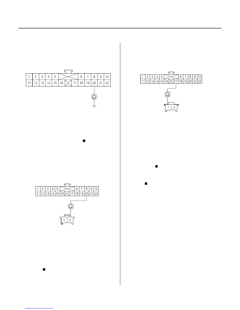
4. Check for continuity between the No. 20 terminal of

the heater control panel 22P connector and body
ground.

Repair short to body ground in the wire

between the heater control panel and the
evaporator temperature sensor.

Go to step 5.

5. Check for continuity between the No. 20 terminal of

the heater control panel 22P connector and the
No. 2 terminal of the evaporator temperature
sensor 2P connector.

Go to step 6.

Repair open in the wire between the heater

control panel and the evaporator temperature
sensor.

6. Check for continuity between the No. 17 terminal of

the heater control panel 22P connector and the
No. 1 terminal of the evaporator temperature
sensor 2P connector.

Check for loose wires or poor connections at

the heater control panel 22P connector and at the
evaporator temperature sensor 2P connector. If the
connections are good, substitute a known-good
heater control panel, and recheck. If the symptom/
indication goes away, replace the original heater
control panel.

Repair open in the wire between the heater

control panel and the evaporator temperature
sensor.

Wire side of female terminals

Wire side of female terminals

Wire side of female terminals

Wire side of female terminals

Wire side of female terminals

Is ther e continuity?

Is ther e continuity?

Is ther e continuity?

03/07/29 10:10:22 61S0X050_210_0021

*01

*02

*03

S0X4A11G24100050602FAAT30

YES

NO

YES

NO

YES

NO

YES

NO

YES

NO

21-21

Recirculation Control Motor Circuit Troubleshooting

BLK/YEL

RECIRCULATION CONTROL MOTOR
7P CONNECTOR

HEATER CONTROL PANEL 22P CONNECTOR

GRN/WHT

GRN/RED

HEATER CONTROL PANEL 22P CONNECTOR

GRN/WHT

GRN/RED

1. Check the No. 3 (7.5A) fuse in the driver’s under-

dash fuse/relay box.

Go to step 2.

Replace the fuse, and recheck.

2. Disconnect the recirculation control motor 7P

connector.

3. Turn the ignition switch ON (II).

4. Measure the voltage between the No. 1 terminal of

the recirculation control motor 7P connector and
body ground.

Go to step 5.

Repair open in the wire between the No. 3

fuse in the driver’s under-dash fuse/relay box and
the recirculation control motor.

5. Turn the ignition switch OFF.

6. Test the recirculation control motor (see page 21-

39).

Go to step 7.

Go to step 12.

7. Disconnect the heater control panel 22P connector.

8. Check for continuity between the No. 1 and No. 11

terminals of the heater control panel 22P connector
and body ground individually.

Repair any short to body ground in the

wire(s) between the heater control panel and the
recirculation control motor.

Go to step 9.

9. Turn the ignition switch ON (II), and check the same

terminals for voltage.

Repair any short to power in the wire(s)

between the heater control panel and the
recirculation control motor. This short may also
damage the heater control panel. Repair the short
to power before replacing the heater control
panel.

Go to step 10.

(cont’d)

Wire side of female terminals

Wire side of female terminals

Wire side of female terminals

Is the f use OK ?

Is ther e batter y voltage?

Is the r ecir culation contr ol motor OK ?

Is ther e continuity?

Is ther e any voltage?

03/07/29 10:10:23 61S0X050_210_0022

*04

*01

S0X4A00G24113614602FAAT10

YES

NO

YES

NO

YES

NO

YES

NO

YES

NO

21-22

21-22

Heating/Air Conditioning

Recirculation Control Motor Circuit
Troubleshooting (cont’d)

Blower Motor Circuit
Troubleshooting

HEATER CONTROL PANEL 22P CONNECTOR

GRN/RED

GRN/RED

GRN/WHT

GRN/WHT

RECIRCULATION CONTROL MOTOR 7P CONNECTOR

HEATER FAN SWITCH 7P CONNECTOR

BLU/YEL

BLU/BLK

BLU/RED

BLU

10. Turn the ignition switch off.

11. Check for continuity between the following

terminals of the heater control panel 22P connector
and the recirculation control motor 7P connector.
22P:

7P:

No. 1

No. 7

No. 11

No. 5

Check for loose wires or poor connections at

the heater control panel 22P connector and at
recirculation control motor 7P connector. If the
connections are good, substitute a known-good
heater control panel, and recheck. If the symptom/
indication goes away, replace the original heater
control panel.

Repair any open in the wire(s) between the

heater control panel and the recirculation control
motor.

12. Remove the recirculation control motor (see page

21-39).

13. Check the recirculation control linkage and doors

for smooth movement.

Replace the recirculation control motor.

Repair the recirculation control linkage or

doors.

1. Turn the ignition switch ON (II) and the heater fan

switch ON.

Go to step 2.

Go to step 16.

2. Turn the heater fan switch OFF.

3. Make sure the ignition switch is ON (II).

Go to step 4.

Go to step 9.

4. Turn the ignition switch OFF.

5. Disconnect the blower motor 2P connector.

6. Disconnect the blower resistor 5P connector.

7. Disconnect the heater fan switch 7P connector.

8. Check for continuity between the No. 3, 4, 5 and 6

terminals of the heater fan switch 7P connector and
body ground individually.

Repair any short to body ground in the

wire(s) between the blower motor, the blower
resistor and the heater fan switch.

Replace the heater fan switch.

Wire side of female terminals

Wire side of female terminals

Wire side of female terminals

Is ther e continuity?

Do the r ecir culation contr ol linkage and door s
move smoothly?

Does the blower r un?

Does the blower motor r un?

Is ther e continuity?

03/07/29 10:10:23 61S0X050_210_0023

*02

*03

*04

YES

NO

YES

NO

YES

NO

21-23

BLOWER RESISTOR

HEATER FAN SWITCH 7P CONNECTOR

BLU/YEL

BLU/BLK

BLU/RED

BLU

BLOWER MOTOR 2P CONNECTOR

JUMPER
WIRE

BLU/RED

9. Turn the ignition switch OFF.

10. Disconnect the blower resistor 5P connector.

11. Measure the resistance between the No. 1 and

No. 5 terminals of the blower resistor.

Go to step 12.

Replace the blower resistor.

12. Reconnect the blower resistor 5P connector.

13. Disconnect the heater fan switch 7P connector.

14. Turn the ignition switch ON (II).

15. Ground each of the heater fan switch 7P connector

terminals individually in the following order: No. 3,
4, 5 and 6.

Replace the heater fan switch.

Repair any open or cause of excessive

resistance in the appropriate wire(s) between the
blower resistor and the heater fan switch.

16. Turn the heater fan switch OFF and the ignition

switch OFF.

17. Check the No. 56 (40A) fuse in the under-hood

fuse/relay box, and the No. 3 (7.5A) fuse in the
driver’s under-dash fuse/relay box.

Go to step 18.

Replace the fuse(s), and recheck.

18. Connect the No. 2 terminal of the blower motor 2P

connector to body ground with a jumper wire.

(cont’d)

Wire side of female terminals

Wire side of female terminals

Is ther e about 3

3.5

?

Does the blower motor r un at pr ogr essively higher
speeds?

Ar e the f uses OK ?

03/07/29 10:10:24 61S0X050_210_0024


Content   ..  384  385  386  387   ..