Honda Odyssey 2004. Manual - part 382


  Index      Honda     Honda Odyssey 2004 - service repair manual 2004 year


Search            


Content   ..  380  381  382  383   ..


Honda Odyssey 2004. Manual - part 382


*01

21-4

Heating/Air Conditioning

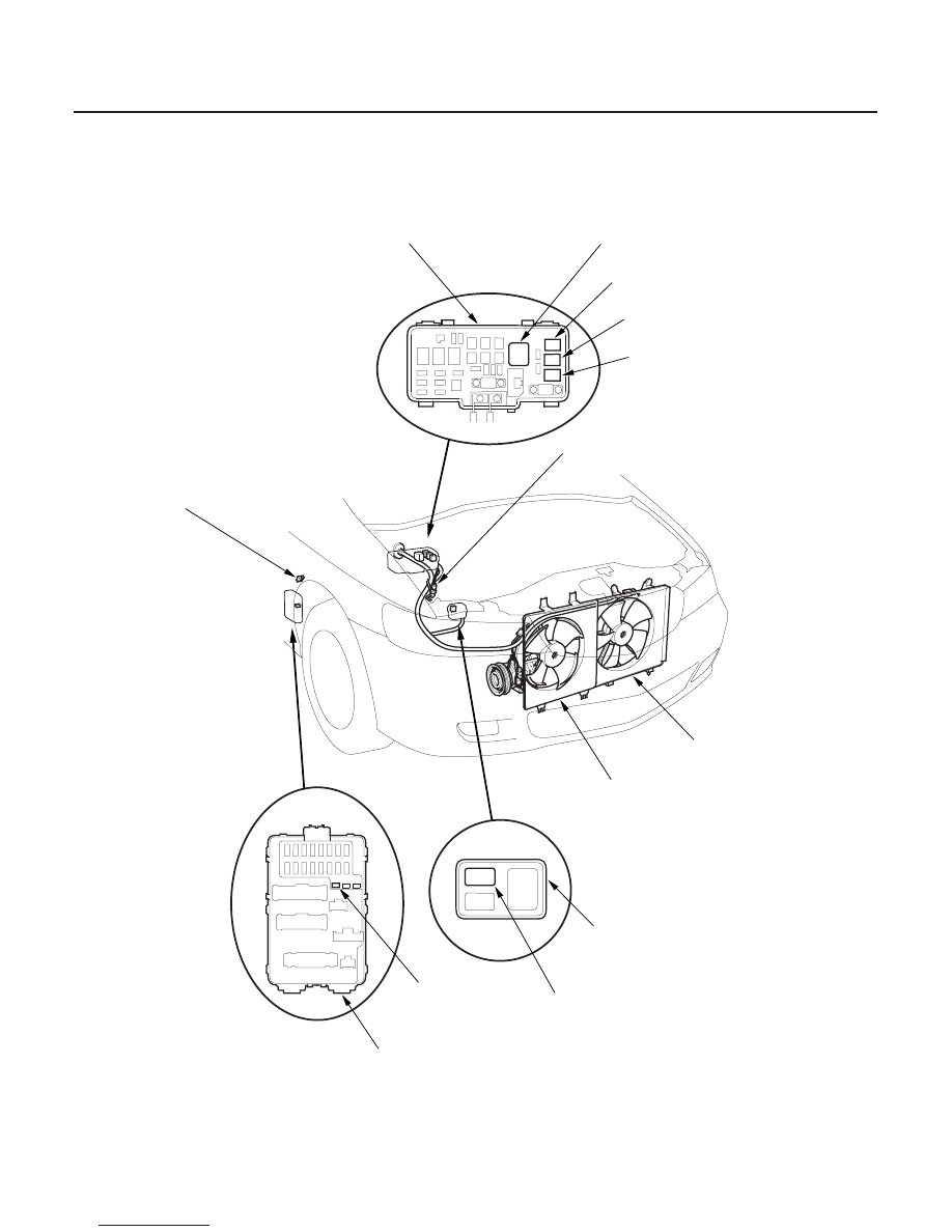
Component Location Index (cont’d)

A/C PRESSURE SWITCH

RADIATOR FAN

CONDENSER FAN

A/C DIODE B,
A/C DIODE C
(Located under-dash,
taped to harness)

UNDER-HOOD FUSE/RELAY BOX

BLOWER MOTOR RELAY

CONDENSER FAN RELAY

RADIATOR FAN RELAY

A/C COMPRESSOR CLUTCH RELAY

ABS RELAY BOX

FAN CONTROL RELAY

A/C DIODE A

PASSENGER’S UNDER-DASH FUSE/RELAY BOX

Test, page 22-88

Test, page 22-88

Test, page 22-88

Test, page 22-88

Test, page 22-88

03/07/29 10:09:39 61S0X050_210_0005

02

21-5

RECIRCULATION CONTROL MOTOR

BLOWER UNIT

BLOWER UNIT COMPONENTS

HEATER VALVE CABLE

DUST ANT POLLEN FILTER

EVAPORATOR

EVAPORATOR COMPONENTS

HEATER UNIT/CORE

EVAPORATOR TEMPERATURE SENSOR

MODE CONTROL MOTOR

AIR MIX CONTROL MOTOR

BLOWER RESISTOR

REAR HEATER-A/C MAIN SWITCH

HEATER CONTROL PANEL

HEATER FAN SWITCH

Test, page 21-39
Replacement, page 21-39

Removal and Installation, page 21-45

Replacement, page 21-45

Adjustment, page 21-48

Replacement, page 21-44

Removal and Installation, page 21-42

Replacement, page 21-43

Replacement, page 21-46

Test, page 21-40

Test, page 21-38
Replacement, page 21-38

Test, page 21-37
Replacement, page 21-37

(With rear A/C)

Removal and Installation, page 21-41
Disassembly and Reassembly, page 21-41

Test, page 21-40

03/07/29 10:09:43 61S0X050_210_0006

S0X4A00G10100000000BAAT20

*01

S0X4A00G10100050652KBAT20

21-6

21-6

Heating/Air Conditioning

A/C Service Tips and Precautions

A/C Refrigerant Oil Replacement

REMOVED
COMPRESSOR

NEW
COMPRESSOR

SAME LEVEL

: A

DRAINING
VOLUME

A: 210 m (7 fl·oz)

• Compressed air mixed with R-134a forms a

combustible vapor.

• The vapor can burn or explode causing serious

injury.

• Never use compressed air to pressure test

R-134a service equipment or vehicle air
conditioning systems.

• Air conditioning refrigerant or lubricant vapor

can irritate your eyes, nose, or throat.

• Be careful when connecting service equipment.
• Do not breathe refrigerant or vapor.

The air conditioning system uses HFC-134a (R-134a)
refrigerant and polyalkyleneglycol (PAG) refrigerant oil,
which are not compatible with CFC-12 (R-12) refrigerant
and mineral oil. Do not use R-12 refrigerant or mineral
oil in this system, and do not attempt to use R-12
servicing equipment; damage to the air conditioning
system or your servicing equipment will result.
Use only service equipment that is U.L.-listed and is
certified to meet the requirements of SAE J2210 to
remove R-134a from the air conditioning system.

If accidental system discharge occurs, ventilate work
area before resuming service.

R-134a service equipment or vehicle air conditioning
systems should not be pressure tested or leak tested
with compressed air.

Additional health and safety information may be
obtained from the refrigerant and lubricant
manufacturers.

• Always disconnect the negative cable from the

battery whenever replacing air conditioning parts.

• Keep moisture and dirt out of the system. When

disconnecting any lines, plug or cap the fittings
immediately; don’t remove the caps or plugs until
just before you reconnect each line.

• Before connecting any hose or line, apply a few drops

of refrigerant oil to the O-ring.

• When tightening or loosening a fitting, use a second

wrench to support the matching fitting.

• When discharging the system, use a R-134a

refrigerant recovery/recycling/charging station; don’t
release refrigerant into the atmosphere.

Recommended PAG oil: DENSO ND-OIL 8:

• P/N 38897-PR7-A01AH: 120 m (4 fl·oz)
• P/N 38899-PR7-A01: 40 m (1 1/3 fl·oz)

Add the recommended refrigerant oil in the amount
listed if you replace any of the following parts.

• To avoid contamination, do not return the oil to the

container once dispensed, and never mix it with other
refrigerant oils.

• Immediately after using the oil, reinstall the cap on

the container, and seal it to avoid moisture
absorption.

• Do not spill the refrigerant oil on the vehicle; it may

damage the paint; if it gets on the paint, wash it off
immediately.

...........
...........

.........

....

........

...........
...........

.........

....

........

Condenser

.35 m (1 1/6 fl·oz)

Evaporator

.40 m (1 1/3 fl·oz)

Line or hose

.10 m (1/3 fl·oz)

Leakage repair

.25 m (5/6 fl·oz)

Compressor

.For compressor replacement,

subtract the volume of oil drained
from the removed compressor from
210 m (7 fl·oz), and drain the
calculated volume of oil from the
new compressor: 210 m (7 fl·oz)
Volume of removed compressor =
Volume to drain from new
compressor.

NOTE: Even if no oil is drained from
the removed compressor, don’t
drain more than 50 m (1 2/3 fl·oz)
from the new compressor.

03/07/29 10:09:44 61S0X050_210_0007

01

21-7

EVAPORATOR

SUCTION HOSE

RECEIVER
LINE

DISCHARGE
HOSE

RECEIVER/DRYER

CONDENSER

COMPRESSOR
BRACKET

COMPRESSOR

Discharge hose to the compressor (6 x 1.0 mm) : 9.8 N·m (1.0 kgf·m, 7.2 lbf·ft)

Receiver line to the evaporator : 13 N·m (1.3 kgf·m, 9.4 lbf·ft)

Suction hose to the compressor (6 x 1.0 mm) : 9.8 N·m (1.0 kgf·m, 7.2 lbf·ft)

Compressor bracket to the engine block (10 x 1.25 mm) : 44 N·m (4.5 kgf·m, 33 lbf·ft)

Compressor to the compressor bracket (8 x 1.25 mm) : 22 N·m (2.2 kgf·m, 16 lbf·ft)

Discharge hose to the condenser (6 x 1.0 mm) : 9.8 N·m (1.0 kgf·m, 7.2 lbf·ft)
Receiver line to the condenser (6 x 1.0 mm) : 9.8 N·m (1.0 kgf·m, 7.2 lbf·ft)

Suction line to the evaporator : 31 N·m (3.2 kgf·m, 23 lbf·ft)
Suction hose to the suction line : 31 N·m (3.2 kgf·m, 23 lbf·ft)

03/07/29 10:09:44 61S0X050_210_0008


Content   ..  380  381  382  383   ..