Honda Odyssey 2004. Manual - part 357
*01
S0X4A00J26220222271KDAT00
01
S0X4A00J26220219291KDAT00
20-70
20-70
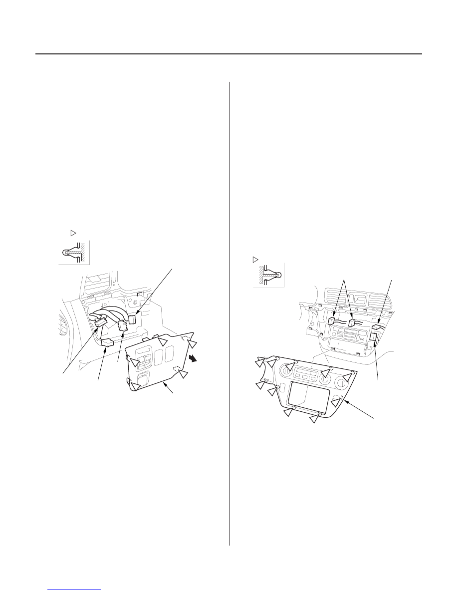
Dashboard
Driver’s Switch Panel Removal/
Installation
Center Panel Removal/Installation
A
Fastener Locations
: Clip, 5
B, C
D
E
B
C
F
G
B
C
C
Fastener Locations
: Clip, 10
B
C
D
A
NOTE:
• When prying with a flat-tip screwdriver, wrap it with
protective tape, and apply protective tape around the
related parts, to prevent damage.
• Take care not to scratch the dashboard and related
parts.
1. Gently pull out on the driver’s switch panel (A) to
release the right clips (B), then detach the
remaining clips (C). If equipped, disconnect the
cruise control main switch connector (D), TCS
switch connector (E), power mirror switch
connector (F) and power sliding door switch
connector (G), then remove the panel.
2. Install the panel in the reverse order of removal,
and note these items:
• Make sure each connector is plugged in properly
(if equipped).
• Push the clips into place securely.
NOTE:
• When prying with a flat-tip screwdriver, wrap it with
protective tape, and apply protective tape around the
related parts, to prevent damage.
• Take care not to scratch the dashboard and related
parts.
1.
page 17-25).
2. Carefully detach the clips, then remove the center
panel (A). Disconnect the heater control panel
connectors (B) or climate control unit connectors,
rear A/C control dial (C) (for some models) and
interior light switch connector (D). With navigation
system, disconnect the hazard warning switch
connector, rear A/C control dial, and interior light
switch connector. For ’03-04 models: Disconnect
the passenger’s airbag off indicator connector.
3. Install the panel in the reverse order of removal,
and note these items:
• Make sure each connector is plugged in properly.
• Push the clips into place securely.
03/07/29 10:01:51 61S0X050_200_0072
Remove the steering column covers (see step 4 on