Honda Odyssey 2004. Manual - part 347


  Index      Honda     Honda Odyssey 2004 - service repair manual 2004 year


Search            


Content   ..  345  346  347  348   ..


Honda Odyssey 2004. Manual - part 347


08

09

*02

11

20-30

Doors

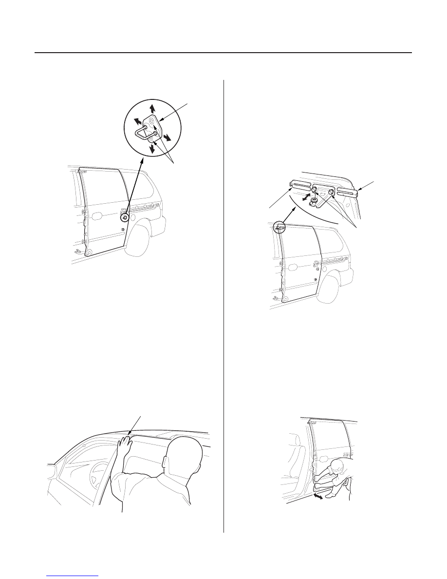
Sliding Door Position Adjustment (cont’d)

8 x 1.25 mm
18 N·m
(1.8 kgf·m,
13 lbf·ft)

A

6 x 1.0 mm
9.8 N·m
(1.0 kgf·m,
7.2 lbf·ft)

A

B

SHIM THICKNESS: A=2 mm (0.08 in.)

B=1 mm (0.04 in.)
Max. 3 mm (0.1 in.)

8. Loosen the striker screws.

9. Adjust the striker (A) in or out to make the rear of

the door overhang the rear panel about 0.5 mm
(0.02 in.) (but not more than 1 mm (0.04 in.)). Then
adjust the striker up or down to center it in the latch
when the door closes. When you’re finished with
this adjustment, torque the striker screws to 18 N·m
(1.8 kgf·m, 13 lbf·ft).

NOTE: Make sure the striker is level after your
adjustments.

10. Close the sliding door, then check if it is flush with

the front door.

• If the sliding door is flush, go to step 12.
• If the sliding door is not flush, go to step 11.

11. Loosen the upper roller bolts, then add or remove

shims under the upper roller to make the sliding
door flush with the body and the front door. Do not
shim the door more than 3 mm. When you’re
finished with this adjustment, torque the upper
roller bolts.

NOTE: Adding or removing shims will change door
flushness only at the upper front corner.

12. Open the front door on the side you’re working on.

13. Check the tightness of the sliding door by

vigorously pulling in and out on the leading edge,
about 1/3 of the way up from the bottom. The door
should fit tightly against the seals. Also inspect the
top to bottom position at the front of the sliding
door, using the center body line as a reference to
the front door.

• If the door does not fit tightly, go to step 14.
• If the door fits tightly, go to step 15.

Front and rear doors should be flush.

03/07/29 10:00:17 61S0X050_200_0032

12

13

14

15

20-31

8 x 1.25 mm
22 N·m
(2.2 kgf·m, 16 lbf·ft)

6 x 1.0 mm
9.8 N·m
(1.0 kgf·m,
7.2 lbf·ft)

A

A

6 x 1.0 mm
8 N·m
(0.8 kgf·m,
6 lbf·ft)

A

14. Loosen the three bolts on the lower roller (A). Move

the door up or down to align the body lines and to
provide good junction switch contact. Loosen the
lower roller bottom nut to adjust the door in or out
until the door is held tightly against the seals.
When you’re finished with this adjustment, torque
the three top bolts, and torque the bottom nut.

NOTE: For best junction switch contact, make sure
there is minimal in and out movement at the front
of the door while keeping the door flush to the body.

15. Remove the weatherstrip (A) from the rear edge of

the door opening.

16. Turn on the power sliding door main switch.

17. Hold a piece of paper over the door cushion, then

close the door with the paper trapped between the
cushion and the door. Make sure not to pinch the
weatherstrip.

18. Pull out the paper.

• If the paper is held tight, but you can pull it out

without ripping it, go to step 19.

• If the paper rips or is not held tight, adjust the

door cushion until the paper is held tight but you
can pull it out without ripping it.
Then go to step 19.

19. Tighten the bolts on the female stops (A) to the

point where the stops can move but will still hold
their position.

20. Close the sliding door, then open it.

21. Carefully tighten the stop bolts, alternating

between the top and the bottom bolt, until all four
bolts are torqued.

NOTE: The stop will pivot if you apply too much
torque to one bolt while the other is loose.

03/07/29 10:00:18 61S0X050_200_0033

*01

S0X4A00J34300000000DAAT00

20-32

Mirrors

Component Location Index

MIRROR MOUNT COVER

MIRROR MOUNT COVER

MOUNT

SPRING

POWER MIRROR

MANUAL MIRROR

REARVIEW MIRROR

MIRROR HOLDER

MIRROR HOLDER

POWER MIRROR ACTUATOR

ACCESS LID

MIRROR BASE

MIRROR BASE

FRICTION WIRE
(’00-04 models)

Replacement, page 20-33

Replacement, page 20-34

Replacement, page 20-36

Replacement, page 20-35

Replacement, page 20-35

Replacement, page 22-185

03/07/29 10:00:20 61S0X050_200_0034

01

02

S0X4A00J34300044051KBAT00

20-33

Power Mirror Replacement

Fastener Location

: Clip, 1

A

Fastener Locations

: Bolt, 4

6 x 1.0 mm
9.8 N·m
(1.0 kgf·m,
7.2 lbf·ft)

C

D

B

A

1. Lower the door glass fully.

2. Carefully pry out the mirror mount cover (A) by

hand as shown.

3. Remove the door panel (see page 20-7).

4. Disconnect the connector (A), and detach the

harness clip (B), then remove the bolts securing the
mirror. While holding the mirror (C), push out the
clip (D), and remove the mirror. Take care not to
scratch the door.

5. Install the power mirror in the reverse order of

removal, and note these items:

• Make sure the connector is plugged in properly.
• Attach the harness clip.
• Push the cover clip into place securely.

03/07/29 10:00:20 61S0X050_200_0035


Content   ..  345  346  347  348   ..