Honda Odyssey 2004. Manual - part 331
−
−
−
−
*03
*01
08
YES
NO
TCS DTC
Appropriate Terminal
YES
NO
19-130
ABS/TCS Components
DTC Troubleshooting (cont’d)
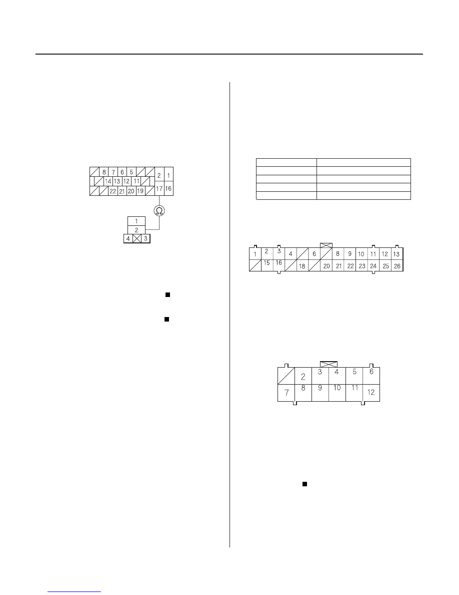
TCS RELAY CONNECTOR
MODULATOR UNIT CONNECTOR
TCS
SOLENOID
(RED/BLU)
ABS/TCS CONTROL UNIT CONNECTOR A (26P)
ABS/TCS CONTROL UNIT CONNECTOR C (12P)
NCR
(GRY)
NOR
(LT BLU)
NOL
(RED/GRN)
NCL
(YEL/GRN)
(YEL/WHT)
FL-OUT
(YEL/GRN) (YEL/BLK)
(RED/BLU) (RED/GRN) (RED/BLK)
(RED/WHT)
(YEL/BLU)
RR-OUT
RL-OUT
FR-OUT
RR-IN
FL-IN
RL-IN
FR-IN
14. Disconnect the modulator unit connector, and
remove the jumper wire from the TCS relay
connector terminal.
15. Check for continuity between the modulator unit
connector terminal No. 17 and the TCS relay
terminal No. 2.
Replace the modulator unit.
Repair open in the wire between the
modulator unit and the TCS relay.
16. Disconnect the modulator unit connector, and
remove the jumper wire from the TCS relay
connector terminal.
17. Check for continuity between the appropriate ABS/
TCS control unit connector A (26P) terminal and all
other ABS and TCS solenoid circuit terminals (see
table).
24: NOR
No. 16
25: NCR
No. 15
26: NOL
No. 3
27: NCL
No. 2
Repair short in the appropriate wires
between the ABS/TCS control unit and the
modulator unit.
Go to step 18.
Terminal side of female terminals
Terminal side of female terminals
Wire side of female terminals
Wire side of female terminals
Is ther e continuity?
Is ther e continuity?
03/07/29 09:57:45 61S0X050_190_0130