Honda Odyssey 2004. Manual - part 296


  Index      Honda     Honda Odyssey 2004 - service repair manual 2004 year


Search            


Content   ..  294  295  296  297   ..


Honda Odyssey 2004. Manual - part 296


*03

05

*04

*05

REAR DISC BRAKE TYPE: ’02-04 models

18-24

Rear Suspension

Hub/Bearing Replacement (cont’d)

B

A
12 x 1.25 mm
108 N·m
(11.0 kgf·m,
79.6 lbf·ft)

A

12 x 1.25 mm
55 N·m (5.6 kgf·m,
41 lbf·ft)

B
24 x 1.5 mm
245 N·m
(25.0 kgf·m,
181 lbf·ft)

A

A
6 x 1.0 mm
9.8 N·m
(1.0 kgf·m, 7.2 lbf·ft)

8 x 1.25 mm

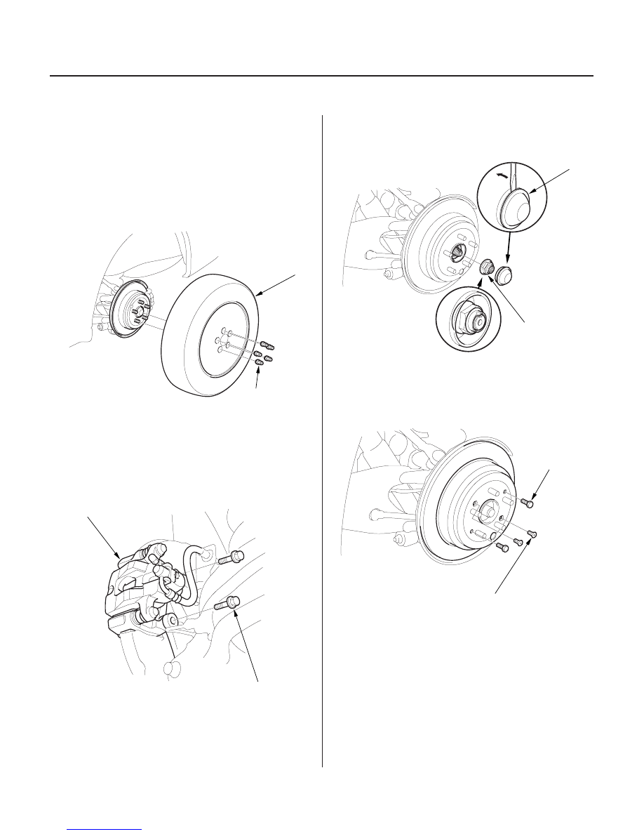
1. Loosen the wheel nuts slightly.

2. Raise the rear of the vehicle, and support it with

safety stands in the proper locations
(see page 1-15).

3. Remove the wheel nuts (A) and rear wheel (B).

4. Remove the caliper mounting bolts, and hang the

caliper assembly (A) to one side. To prevent
damage to the caliper assembly or brake hose, use
a short piece of wire to hang the caliper from the
undercarriage.

5. Press the parking brake pedal.

6. Remove the hub cap (A).

7. Raise the locking tab on the spindle nut (B), then

remove the nut.

8. Remove the drum in brake disc retaining screws (A).

9. Release the parking brake pedal, and remove the

drum in brake disc.

10. Screw two 8 x 1.25 mm bolts into the drum in brake

disc to push it away from the hub. Turn each bolt
two turns at a time to prevent cocking the drum in
brake disc excessively.

03/07/29 09:51:18 61S0X050_180_0024

08

18-25

11. Remove the hub bearing unit.

12. Check the rear hub for damage and cracks.

13. Install the hub bearing unit in the reverse order of

removal, and pay particular attention to the
following items:

• Wash the bearing and spindle thoroughly in high

flash point solvent before reassembly.

• Before installing the new spindle nut, apply a

small amount of engine oil to the seating surface
of the nut.

• After tightening, use a drift to stake the spindle

nut shoulder against the spindle.

• Inspect the pulser teeth for any damage.

03/07/29 09:51:18 61S0X050_180_0025

01

*02

03

*01

S0X4A00B44100062201KDAT00

Special Tools Required

18-26

Rear Suspension

Upper Arm Removal/Installation

B

A

07MAC-SL00200

12 x 1.25 mm
49

59 N·m

(5.0

6.0 kgf·m,

36

43 lbf·ft)

A
12 x 1.25 mm
64 N·m
(6.5 kgf·m, 47 lbf·ft)

B

B

A

Ball joint remover, 28 mm 07MAC-SL00200

1. Raise the rear of the vehicle, and support it with

safety stands in the proper locations
(see page 1-15). Remove the rear wheel.

2. Position a floor jack at the connecting point of the

lower arm B and the knuckle (A).

3. Remove the lock pin from the upper ball joint castle

nut, and remove the nut.

4. Remove the upper ball joint from the knuckle using

the special tool (see page 18-10).

5. Remove the upper arm bolt (A). Remove the upper

arm (B) from the vehicle.

6. Install the upper arm.

7. Install the upper arm bolt and castle nut. Tighten

finger tight.

8. Position a floor jack at the connecting point of the

lower arm B and the knuckle (A).

9. Raise the rear suspension with the floor jack until

the vehicle just lifts off the safety stands.

10. Tighten the upper arm bolt to the specific torque

value, and note these items:

• Be careful not to damage the ball joint boot when

connecting the upper arm to the knuckle.

• Tighten the castle nut to the lower torque

specifications, then tighten it only far enough to
align the slot with the hole in the stud. Do not
align the castle nut by loosening it.

• Use a new lock pin in the castle nut.
• Before installing the wheel, clean the mating

surfaces on the brake drum or the drum in brake
disc and the inside of the wheel.

• Check the rear wheel alignment, and adjust it if

necessary (see page 18-5).

03/07/29 09:51:19 61S0X050_180_0026

*01

01

S0X4A00B44100037701KDAT10

18-27

Lower Arm A Removal/Installation

B
14 x 1.5 mm
142 N·m (14.5 kgf·m, 105 lbf·ft)

C
12 x 1.25 mm
64 N·m (6.5 kgf·m,
47 lbf·ft)

A

B

A

1. Raise the rear of the vehicle, and support it with

safety stands in the proper locations
(see page 1-15). Remove the rear wheel.

2. Remove the lower arm A mounting bolt (B).

3. Remove the lower arm mounting nut (C).

4. Remove the lower arm A from the vehicle.

5. Install the lower arm A.

6.

7. Position a floor jack at the connecting point of

lower arm B and the knuckle (A).

Raise the rear suspension with the floor jack until
the vehicle just lifts off the safety stands.

• Before installing the wheel, clean the mating

surfaces on the brake drum or the drum in brake
disc and the inside of the wheel.

necessary (see page 18-5).

03/07/29 09:51:20 61S0X050_180_0027

Hand tighten the mounting bolt and nut.

8.

Check the rear wheel alignment, and adjust it if


specified torque values, and note these items:


9. Tighten the mounting bolt and nut to the


Content   ..  294  295  296  297   ..