Honda Odyssey 2004. Manual - part 289
01
02
03
04
S0X4A00F00000057111KCAT00
17-44
Power Steering
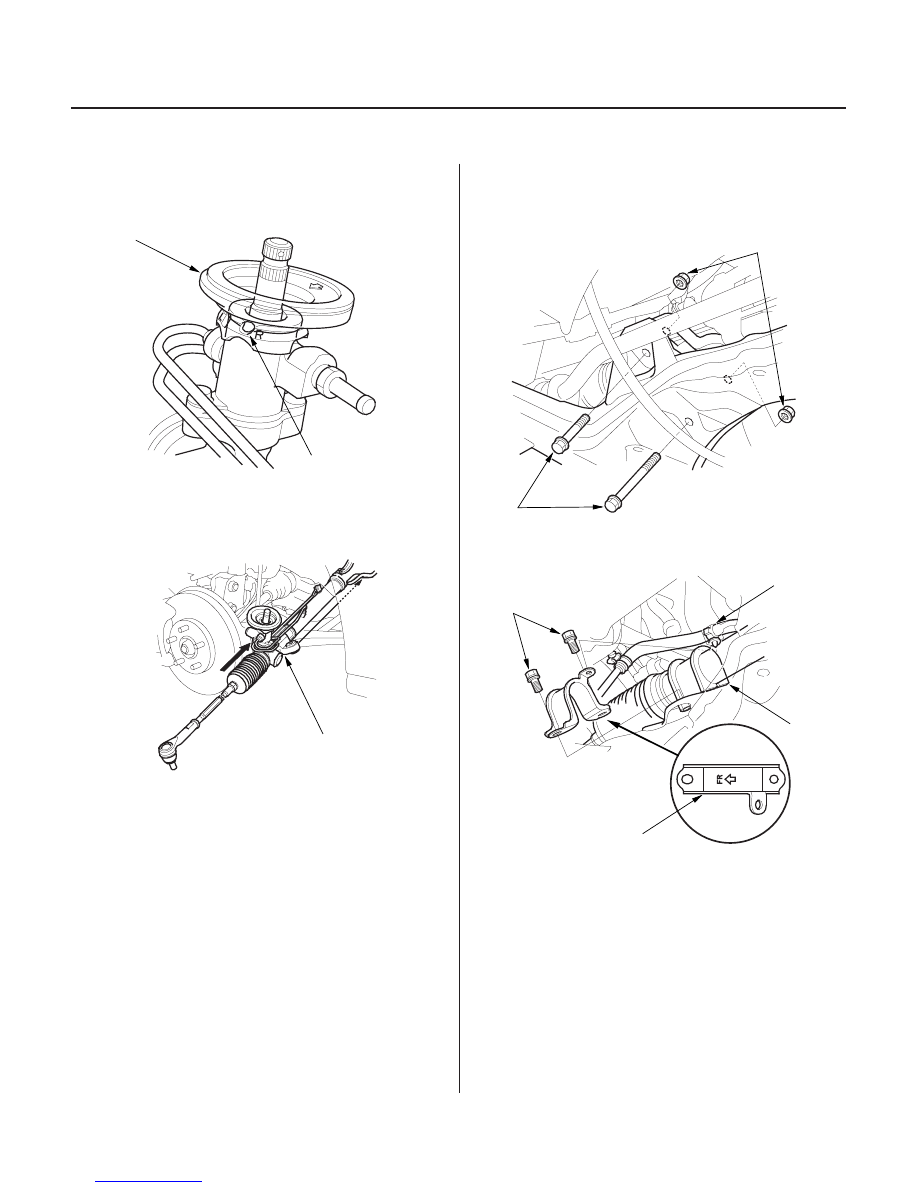
Steering Gearbox Installation
A
B
A
58 N·m
(5.9 kgf·m,
43 lbf·ft)
A
C
39 N·m
(4.0 kgf·m, 29 lbf·ft)
D
A
B
1. Install the pinion shaft grommet (A). Align the slot
(B) in the pinion shaft grommet with the lug portion
on the valve housing.
2. Pass the steering gearbox (A) between the front
subframe and body from the driver’s side. Place the
gearbox in position on the subframe.
3. Loosely install the two 10 mm gearbox mounting
bolts (A).
4. Install the mounting cushion (A) on the right side of
the gearbox.
5. Install the mounting bracket (B) over the mounting
cushion, then install the two 10 mm gearbox
mounting bolts (C). Install the bolts loosely first,
then tighten all four mountig bolts to the specified
torque.
6. Install the clamp for the feed line (D) on the right
mounting bracket.
03/07/29 09:49:42 61S0X050_170_0044