Honda Odyssey 2004. Manual - part 276


  Index      Honda     Honda Odyssey 2004 - service repair manual 2004 year


Search            


Content   ..  274  275  276  277   ..


Honda Odyssey 2004. Manual - part 276


04

*09

03

*10

Grease quantity

Outboard Joint: 110

130 g (3.9

4.6 oz)

16-14

Driveline/Axle

Driveshaft Reassembly (cont’d)

A

B

C

Push.

Push.

10 cm
(4 in.)

A

A

B

A

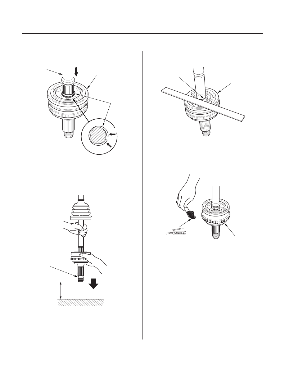
4. Insert the driveshaft (A) into the outboard joint (B)

5. To completely seat the outboard joint, pick up the

from 10 cm (4 in.). Do not use a hammer as
excessive force may damage the driveshaft. Be
careful not to damage the threaded section (A) of
the outboard joint.

6. Check the alignment of the paint mark (A) with the

outboard joint end (B).

7. Pack the outboard joint (A) with the joint grease

included in the new joint boot set.

Use the grease included
in the outboard boot set.

03/07/29 09:47:30 61S0X050_160_0014

driveshaft and joint, and tap it onto a hard surface

until the circlip (C) is closed. 

06

24

04

16-15

A

B

A

C

B

A

6.0 mm
(0.24 in.) MAX

3.0 mm
(0.12 in.) MAX

8. Fit the boot (A) ends onto the driveshaft (B) and

outboard joint (C).

9. Close the ear portion (A) of the band with a

commercially available boot band pincers Kent-
Moore J-35910 or equivalent (B).

10. Check the clearance between the closed ear portion

of the band. If the clearance is not within the
standard, close the ear portion of the band farther.

11. Repeat steps 9 and 10 for the band on the other end

of the boot.

03/07/29 09:47:30 61S0X050_160_0015

01

02

02

01

S0X4A00E16226600000KCAT00

16-16

Driveline/Axle

Driveshaft Installation

A

B

A

E

B

D

A

E

C

D

B

A

C

A

B

E

D
12 x 1.25 mm
59

69 N·m

(6.0

7.0 kgf·m,

43

51 lbf·ft)

1. Apply 0.3

1.0 g (0.01

0.04 oz) ’99-01 models, 0.5

1.0 g (0.02

0.04 oz) ’02-04 models of specified

grease to the whole splined surface (A) of the left
driveshaft. After applying grease, remove the
grease from the splined grooves at intervals of
2

3 splines and from the set ring groove (B) so

that air can bleed from the intermediate shaft.

2. Install a new set ring into the set ring groove of the

driveshaft (intermediate shaft).

3. Clean the areas where the driveshaft contacts the

differential thoroughly with solvent or brake
cleaner, and dry with compressed air. Insert the
inboard end (A) of the driveshaft into the
differential (B) or intermediate shaft (C) until the set
ring (D) locks in the groove (E).

4. Install the outboard joint (A) into the front hub (B).

5. Install the knuckle (A) onto the lower arm (B). Be

careful not to damage the ball joint boot (C). Wipe
off the grease before tightening the nut at the ball
joint. Torque the castle nut (D) to the lower torque
specification, then tighten it only far enough to
align the slot with the pin hole. Do not align the nut
by loosening it.

6. Install the new lock pin (E) into the pin hole as

shown.

03/07/29 09:47:31 61S0X050_160_0016

05

*01

*01

S0X4A00E16236500000KAAT00

16-17

16-17

Intermediate Shaft Removal

B

A

12 x 1.25 mm
78 N·m
(8.0 kgf·m,
58 lbf·ft)

12 x 1.5 mm
108 N·m
(11.0 kgf·m,
80.0 lbf·ft)

A
24 x 1.5 mm
245 N·m (25.0 kgf·m, 181 lbf·ft)

B

B

A

C

7. Install the stabilizer link (A) on the damper (B).

8. Install a new spindle nut (A), then tighten the nut.

After tightening, use a drift to stake the spindle nut
shoulder (B) against the driveshaft.

9. Clean the mating surfaces of the brake disc and the

front wheel, then install the front wheel with the
wheel nuts.

10. Turn the front wheel by hand, and make sure there

is no interference between the driveshaft and
surrounding parts.

11. Tighten the flange bolts and the self-locking nut

with the vehicle’s weight on the damper.

12. Refill the transmission with recommended fluid:

• 4-speed 1999-2001 automatic transmission (see

page 14-137).

• 5-speed 2002-2004 automatic transmission (see

page 14-368).

13. Check the front wheel alignment, and adjust it if

necessary (see page 18-5).

1. Drain the transmission fluid:

• 4-speed 1999-2001 automatic transmission (see

page 14-137).

• 5-speed 2002-2004 automatic transmission (see

page 14-368).

2. Remove the right driveshaft (see page 16-3).

3. Remove the three dowel bolts (A).

4. Remove the intermediate shaft (B) from the

differential. Hold the intermediate shaft horizontal
until it is clear of the differential to prevent damage
to the differential oil seal (C).

03/07/29 09:47:32 61S0X050_160_0017


Content   ..  274  275  276  277   ..