Honda Odyssey 2004. Manual - part 273
01
01
01
01
01
01
01
01
01
S0X4A000000000J1601PAAT00
Ref. No.
Tool Number
Description
Qty
16-2
Driveline/Axle
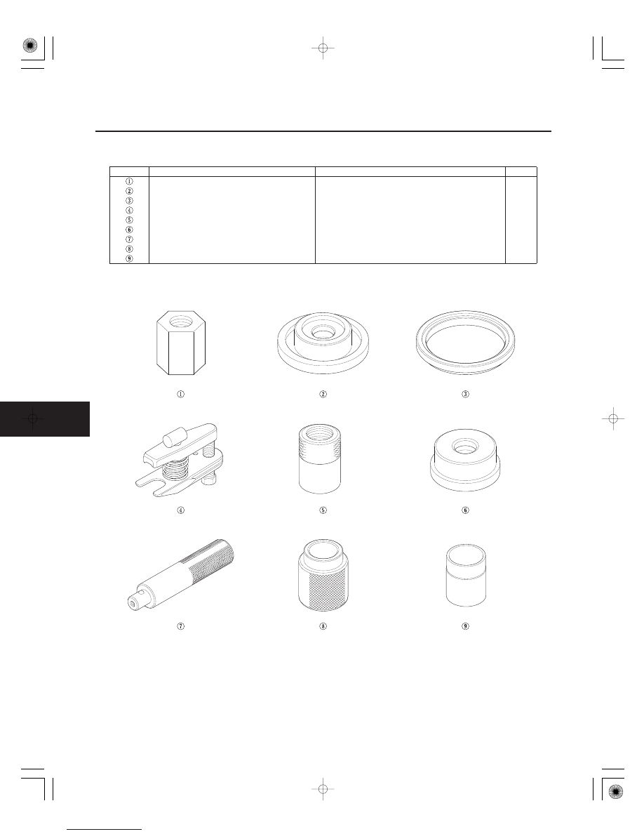
Special Tools
07AAF-SDAA100
Ball Joint Thread Protector
1
07JAD-PH80101
Oil Seal Driver Attachment
1
07LAF-SM40300
Support Base Attachment
1
07MAC-SL00100
Ball Joint Remover, 32 mm
1
07XAC-001020A
Threaded Adapter, 24 x 1.5 mm
1
07746-0010300
Attachment, 42 x 47 mm
1
07749-0010000
Driver
1
07947-4630100
Fork Seal Driver, 39.2 x 49.5 x 15 mm
1
07965-SD90100
Support Base
1
03/07/29 09:47:21 61S0X050_160_0002