Honda Odyssey 2004. Manual - part 272


  Index      Honda     Honda Odyssey 2004 - service repair manual 2004 year


Search            


Content   ..  270  271  272  273   ..


Honda Odyssey 2004. Manual - part 272


01

01

Standard:
New bearing:

2.7

3.9 N·m

(28

40 kgf·cm, 24

35 lbf·in.)

Reused bearings:

2.5

3.6 N·m

(25

37 kgf·cm, 22

32 lbf·in.)

14-482

A/T Differential

Carrier Bearing Preload Inspection (cont’d)

10 x 1.25 mm
44 N·m
(4.5 kgf·m, 33 lbf·ft)

H

G

G

C

B

D

A

C

E

F

07YAJ-S3V0100

A

B

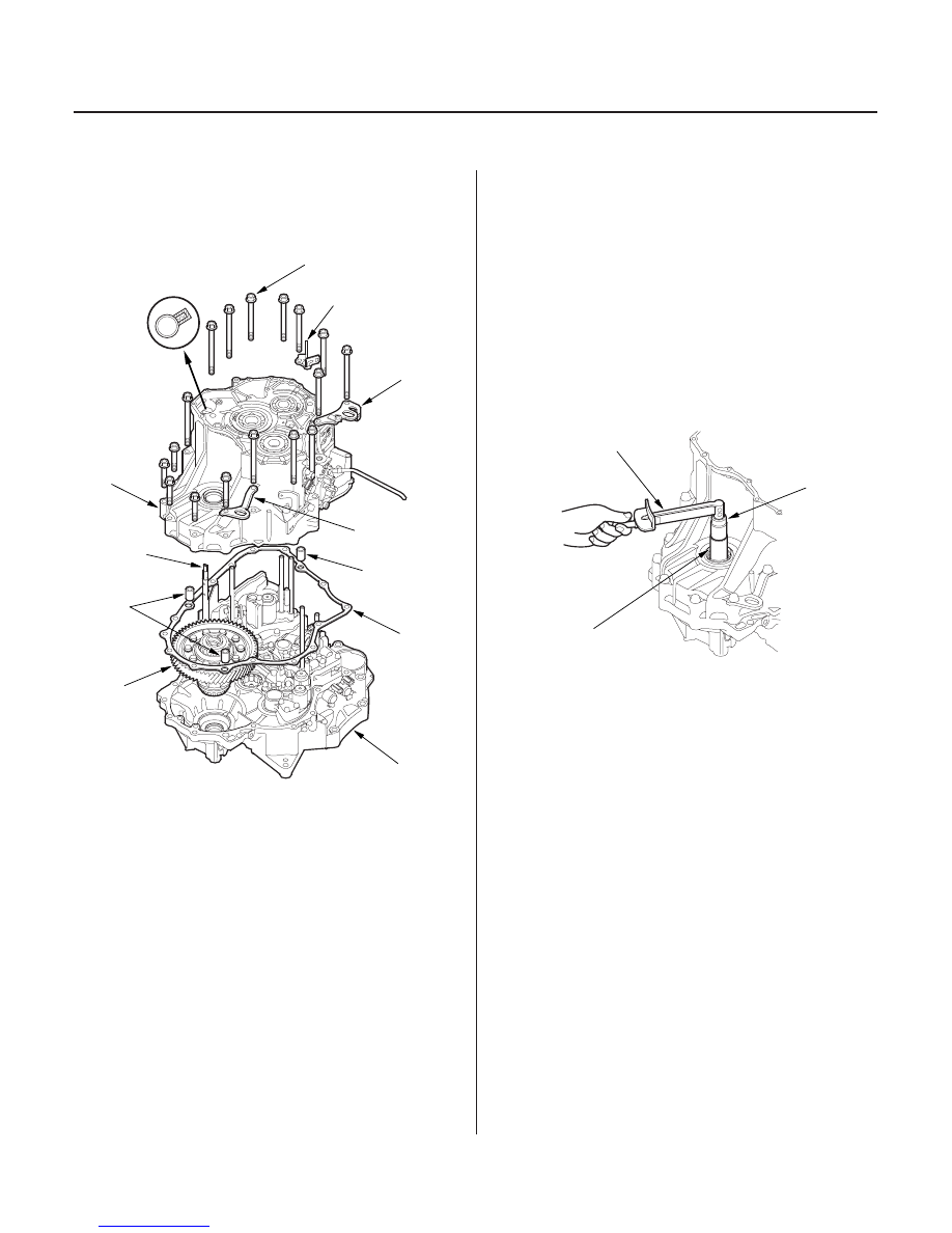
7. Install the differential assembly (A), gasket (B), and

dowel pins (C) on the torque converter housing (D).
Align the spring pin on the control shaft (E) with the
transmission housing groove.

8. Install the transmission housing (F) with the

transmission hangers (G) and harness clamp
bracket (H), then tighten the bolts.

9. Rotate the differential assembly in both directions

to seat the bearings.

10. Measure the starting torque of the differential

assembly with the special tools, a torque
wrench (A) and a socket (B). Measure the starting
torque at normal room temperature in both
directions.

03/07/29 09:46:33 61S0X050_140_0485

THRUST SHIM, 81 mm

No.

Part Number

Thickness

14-483

11. If the measurement is out of standard, remove the

thrust shim and select the thrust shim from table.
Install the new thrust shim and recheck. To
increase the starting torque, increase the thickness
of the thrust shim. To decrease the starting torque,
decrease the thickness of the thrust shim. Changing
the shim to the next size will increase or decrease
starting torque about 0.3

0.4 N·m (3

4 kgf·cm,

2

3 lbf·in.).

A

41438-P7T-700

2.05 mm (0.081 in.)

AA

41438-PGH-000

2.075 mm (0.082 in.)

B

41439-P7T-700

2.10 mm (0.083 in.)

BB

41439-PGH-000

2.125 mm (0.084 in.)

C

41440-P7T-700

2.15 mm (0.085 in.)

CC

41440-PGH-000

2.175 mm (0.086 in.)

D

41441-P7T-000

2.20 mm (0.087 in.)

DD

41441-PGH-000

2.225 mm (0.088 in.)

E

41442-P7T-000

2.25 mm (0.089 in.)

EE

41442-PGH-000

2.275 mm (0.090 in.)

F

41443-P7T-000

2.30 mm (0.091 in.)

FF

41443-PGH-000

2.325 mm (0.092 in.)

G

41444-P7T-000

2.35 mm (0.093 in.)

GG

41444-PGH-000

2.375 mm (0.094 in.)

H

41445-P7T-000

2.40 mm (0.094 in.)

HH

41445-PGH-000

2.425 mm (0.095 in.)

I

41446-P7T-000

2.45 mm (0.096 in.)

II

41446-PGH-000

2.475 mm (0.097 in.)

J

41447-P7T-000

2.50 mm (0.098 in.)

JJ

41447-PGH-000

2.525 mm (0.099 in.)

K

41448-P7T-000

2.55 mm (0.100 in.)

KK

41448-PGH-000

2.575 mm (0.101 in.)

L

41449-P7T-000

2.60 mm (0.102 in.)

LL

41449-PGH-000

2.625 mm (0.103 in.)

M

41450-P7T-000

2.65 mm (0.104 in.)

MM

41450-PGH-000

2.675 mm (0.105 in.)

N

41451-P7T-000

2.70 mm (0.106 in.)

NN

41451-PGH-000

2.725 mm (0.107 in.)

O

41452-P7T-000

2.75 mm (0.108 in.)

OO

41452-PGH-000

2.775 mm (0.109 in.)

P

41453-P7T-000

2.80 mm (0.110 in.)

PP

41453-PGH-000

2.825 mm (0.111 in.)

Q

41454-P7T-000

2.85 mm (0.112 in.)

QQ

41454-PGH-000

2.875 mm (0.113 in.)

R

41455-P7T-000

2.90 mm (0.114 in.)

RR

41455-PGH-000

2.925 mm (0.115 in.)

S

41456-P7T-000

2.95 mm (0.116 in.)

SS

41456-PGH-000

2.975 mm (0.117 in.)

T

41457-P7T-000

3.00 mm (0.118 in.)

TT

41457-PGH-000

3.025 mm (0.119 in.)

U

41458-P7T-000

3.05 mm (0.120 in.)

03/07/29 09:46:34 61S0X050_140_0486

S0X4A000000000J1403ZAAT00

03/07/29 09:46:34 61S0X050_140_0487

S0X4A000000000J1601ZCAT00

Transaxle

Driveline/Axle

................................................................

..................................................

.....................................................

..............................................

...............................................

.................................................

.......................................

................................

.................................

...................................

Special Tools

. 16-2

Driveshaft Inspection

. 16-3

Driveshaft Removal

. 16-3

Driveshaft Disassembly

. 16-5

Driveshaft Reassembly

. 16-9

Driveshaft Installation

. 16-16

Intermediate Shaft Removal

. 16-17

Intermediate Shaft Disassembly

. 16-18

Intermediate Shaft Reassembly

. 16-19

Intermediate Shaft Installation

. 16-21

03/07/29 09:47:20 61S0X050_160_0001


Content   ..  270  271  272  273   ..