Honda Odyssey 2004. Manual - part 263


  Index      Honda     Honda Odyssey 2004 - service repair manual 2004 year


Search            


Content   ..  261  262  263  264   ..


Honda Odyssey 2004. Manual - part 263


*01

*02

S0X4AA1E10410917451KCAT30

Special Tools Required

14-446

Shafts and Clutches

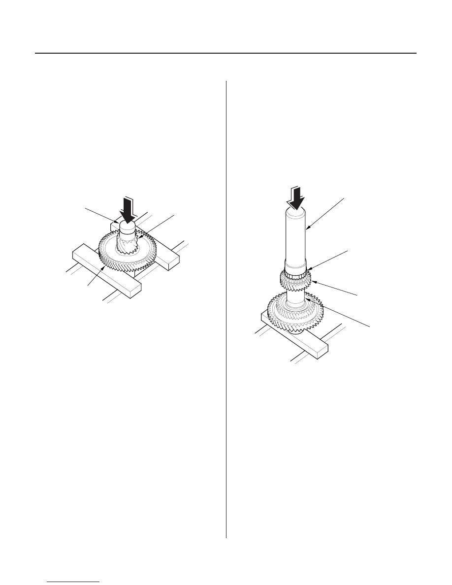
Countershaft 4th Gear and Reverse Selector Hub Installation

B

C

A

07746-0030100

A

B

C

Driver, 40 mm I.D. 07746-0030100

1. Apply ATF to the parts.

2. Install the 1st gear on the countershaft by hand.

3. Align the shaft splines with those on 4th gear, then

press the countershaft (A) into the 4th gear with a
press. Place a shaft protector (B) between the
countershaft and press to prevent damaging the
countershaft.

4. Stop pressing the countershaft when the 4th gear

contacts the 1st gear (C).

5. Install the 31 mm cotters, 35 x 47 x 45.6 mm

distance collar, 31 mm cotters, 35 x 47 x 7.8 mm
distance collar, snap ring, needle bearing, and 5th
gear (A) on the countershaft.

6. Slide the reverse selector hub (B) over the

countershaft (C), and then press it into place with
the special tool and a press.

NOTE: Some reverse selector hubs are not press-
fitted, and can be installed without using the
special tool and a press.

03/07/29 09:46:00 61S0X050_140_0449

*01

*02

S0X4AA1E10410910421KBAT00

Special Tools Required

14-447

3rd Clutch Ball Bearing Replacement

B

D

A

C

07746-0010500

07749-0010000

• Driver 07749-0010000
• Attachment, 62 x 68 mm 07746-0010500

NOTE: Check the bearing for wear and rough
movement. If the bearing is OK, removal is not
necessary.

1. Remove the ball bearing (A) from the 3rd clutch

with a commercially available bearing puller (B),
bearing separator (C), and stepper adapter (D).

2. Install the new bearing on the 3rd clutch with the

special tools and a press.

03/07/29 09:46:00 61S0X050_140_0450

01

S0X4AA1E10411300000MEAT00

→ →

14-448

Shafts and Clutches

Secondary Shaft Disassembly, Inspection, and Reassembly

226 N·m (23.0 kgf·m, 166 lbf·ft)

0

167 N·m (17.0 kgf·m, 123 lbf·ft)

CONICAL SPRING WASHER

IDLER GEAR

TRANSMISSION
HOUSING BEARING

THRUST NEEDLE
BEARING

THRUST NEEDLE
BEARING

NEEDLE BEARINGS

SECONDARY SHAFT

NEEDLE BEARINGS

1ST GEAR

COTTERS, 32 mm

BALL BEARING

SNAP RING

O-RINGS

2ND GEAR

THRUST NEEDLE
BEARING

COTTER RETAINER

SEALING RINGS, 35 mm

SPLINED WASHER,
38 x 56.5 mm

THRUST NEEDLE
BEARING

THRUST SHIM, 37 x 55 mm

1ST/1ST-HOLD/2ND CLUTCH
ASSEMBLY

LOCKNUT (FLANGE NUT)

1ST-HOLD
CLUTCH HUB

1ST CLUTCH
HUB

1. Remove the locknut, and disassemble the shaft and gears.

2. Inspect the thrust needle bearing and needle bearing for galling and rough movement.

3. Check the clearance of the secondary shaft assembly.

4. Check the splines for excessive wear and damage.

5. Check the shaft bearing surfaces for scoring and excessive wear.

6. Check the idler gear bearing for wear and rough movement. If the bearing is worn or damaged, replace it (see

page 14-451).

7. Before installing the O-rings, wrap the shaft splines with tape to prevent damage to the O-rings.

8. Lubricate all parts with ATF during reassembly.

9. Install the conical spring washer and splined washer in the direction shown.

Replace.

Replace.

Selective part

Selective part

Replace.
Left-hand threads

03/07/29 09:46:01 61S0X050_140_0451

*01

*02

S0X4AA1E10411300000MAAT00

Standard:

0.07

0.15 mm (0.003

0.006 in.)

SPLINED WASHER, 38 x 56.5 mm

No.

Part Number

Thickness

14-449

Secondary Shaft Clearance Inspection

I

A

B

C

D

E

F

G

H

J

F

E

B

J

1. Remove the O-rings from the secondary shaft.

2. Assemble the thrust needle bearing (A), 1st gear

assembly (B), needle bearings (C), thrust needle
bearing (D), 38 x 56.5 mm splined washer (E), 32
mm cotters (F), cotter retainer (G), and snap ring (H)
on the secondary shaft (I).

3. Measure the clearance between the 38 x 56.5 mm

splined washer (E) and 32 mm cotters (F) with a
feeler gauge (J) in at least three places. Use the
average as the actual clearance.

4. If the measurement is out of standard, remove the

splined washer, and measure its thickness.

5. Select and install a new splined washer, then

recheck the clearance.

1

90502-P0Z-000

6.85 mm (0.270 in.)

2

90503-P0Z-000

6.90 mm (0.272 in.)

3

90504-P0Z-000

6.95 mm (0.274 in.)

4

90505-P0Z-000

7.00 mm (0.276 in.)

5

90506-P0Z-000

7.05 mm (0.278 in.)

6

90507-P0Z-000

7.10 mm (0.280 in.)

(cont’d)

03/07/29 09:46:02 61S0X050_140_0452


Content   ..  261  262  263  264   ..