Honda Odyssey 2004. Manual - part 262


  Index      Honda     Honda Odyssey 2004 - service repair manual 2004 year


Search            


Content   ..  260  261  262  263   ..


Honda Odyssey 2004. Manual - part 262


*01

*02

S0X4AA1E10411210251MAAT10
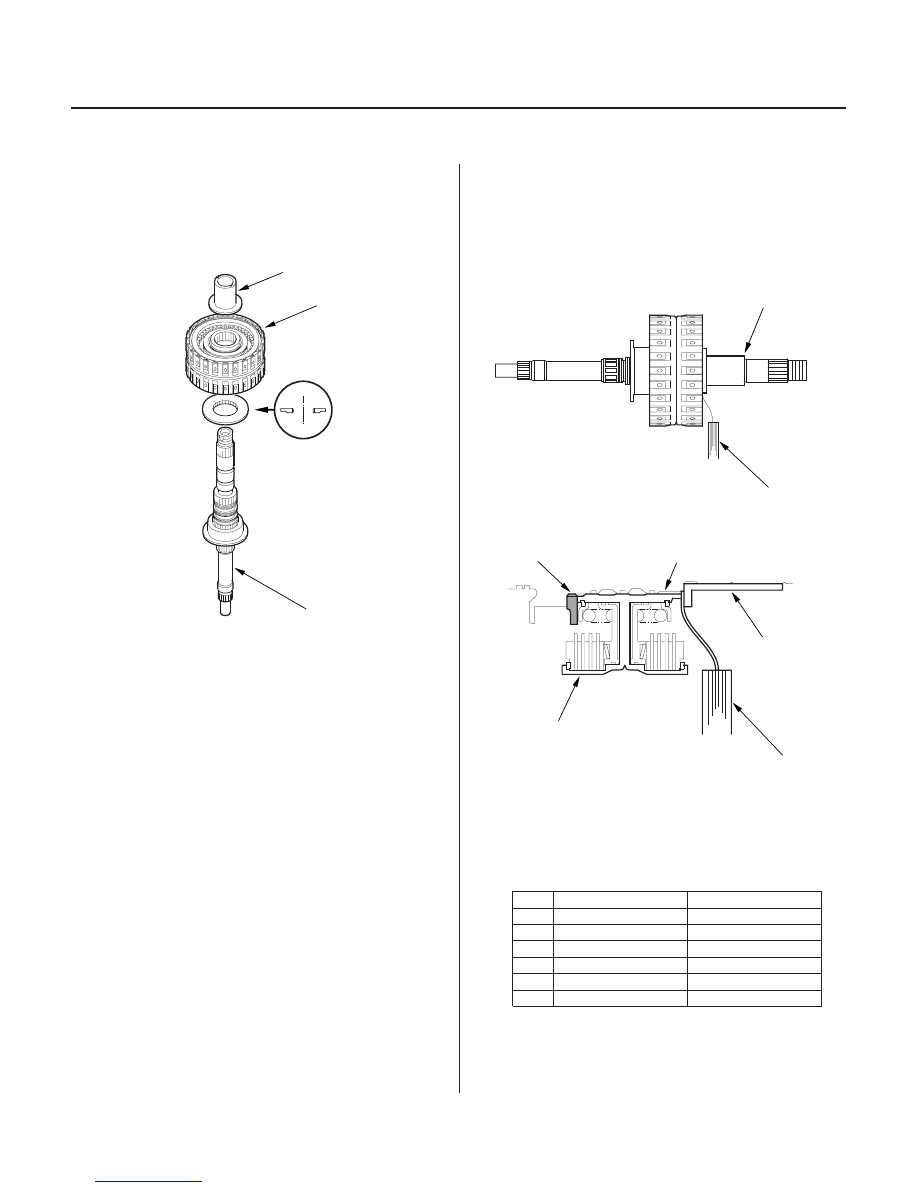
Standard:

0.03

0.11 mm (0.001

0.004 in.)

THRUST SHIM, 41 x 73 mm

No.

Part Number

Thickness

14-442

Shafts and Clutches

4th/5th Clutch Clearance Inspection

A

B

C

D

F

C

A

B

C

E

F

1. Remove the O-rings from the mainshaft.

2. Assemble the 41 x 73 mm thrust shim (A), 4th/5th

clutch assembly (B), and 5th gear collar (C) on the
mainshaft (D).

3. Hold the 5th gear collar (C) against the clutch

assembly (B), then measure the clearance between
the clutch guide (E) and the 5th gear collar with a
feeler gauge (F) in at least 3 places. Use the
average as the actual clearance.

4. If the clearance is out of standard, remove the

thrust shim and measure its thickness.

5. Select and install a new shim, then recheck.

1

90414-P7W-000

7.85 mm (0.309 in.)

2

90415-P7W-000

7.90 mm (0.311 in.)

3

90416-P7W-000

7.95 mm (0.313 in.)

4

90417-P7W-000

8.00 mm (0.315 in.)

5

90418-P7W-000

8.05 mm (0.317 in.)

6

90419-P7W-000

8.10 mm (0.319 in.)

6. After replacing the thrust shim, make sure the

clearance is within standard.

03/07/29 09:45:58 61S0X050_140_0445

*01

*02

S0X4AA1E10411239751KBAT00

14-443

Mainshaft Sealing Ring Replacement

The sealing rings are synthetic resin with chamfered
ends. Check the condition of the sealing rings, and
replace them only if they are worn, distorted, or
damaged.

1. For a better fit, squeeze sealing rings together

slightly before installing them.

2. Apply ATF to the new sealing rings then install

them on the mainshaft.

3. After installing the sealing rings, verify the

following:

• The rings are fully seated in the groove.
• The rings are not twisted.
• The chamfered ends of the rings are properly

joined.

03/07/29 09:45:58 61S0X050_140_0446

*01

S0X4AA1E10410900000MEAT00

→ →

14-444

Shafts and Clutches

Countershaft Disassembly, Inspection, and Reassembly

226 N·m (23.0 kgf·m, 166 lbf·ft)

0

167 N·m (17.0 kgf·m, 123 lbf·ft)

CONICAL SPRING
WASHER

TRANSMISSION
HOUSING BEARING

THRUST NEEDLE
BEARING

4TH GEAR

NEEDLE BEARING

5TH GEAR

COUNTERSHAFT

PARK GEAR

1ST GEAR

COTTERS, 31 mm

BALL BEARING

2ND GEAR

REVERSE GEAR

REVERSE
SELECTOR

SNAP RING, 31 mm

DISTANCE COLLAR,
35 x 47 x 45.6 mm

REVERSE
SELECTOR HUB

LOCKNUT (FLANGE NUT)

NEEDLE BEARING

NEEDLE BEARING

THRUST NEEDLE
BEARING

3RD GEAR

SPLINED WASHER,
31 x 63.5 mm

O-RINGS

3RD CLUTH
ASSEMBLY

DISTANCE COLLAR,
35 x 47 x 7.8 mm

1. Remove the locknut, and take off components down to the reverse selector hub.

2. Remove the reverse selector hub, 4th gear, and 1st gear (see page 14-445).

3. Check the bearing on the 3rd clutch for wear and rough movement. If the bearing is worn or damaged, replace it

(see page 14-447).

4. Inspect the thrust needle bearing and the needle bearing for galling and rough movement.

5. Check the splines for excessive wear and damage.

6. Check the shaft bearing surfaces for scoring and excessive wear.

7. Lubricate all parts with ATF, and reassemble the shafts and gears.

8. Install the distance collars, reverse selector hub, reverse selector, splined washer, and conical spring washer in

the direction shown.

Replace.

Replace.
Left-hand threads

Selective part

Replace.

03/07/29 09:45:59 61S0X050_140_0447

01

02

S0X4AA1E10410917451KAAT30

14-445

Countershaft Reverse Selector Hub and 4th Gear Removal

C

A

B

C

A

B

1. Remove the reverse selector hub (A) and the 5th

gear (B) from the countershaft with a press. Place a
shaft protector (C) between the countershaft and
press to prevent damaging the countershaft.

NOTE: Some reverse selector hubs are not press-
fitted, and can be removed without using a press.

2. Remove the needle bearing, snap ring, 35 x 47 x

7.8 mm distance collar, 31 mm cotters, 35 x 47 x
45.6 mm distance collar, and 31 mm cotters from
the countershaft.

3. Remove the 1st gear (A) and 4th gear (B) from the

countershaft with a press. Place a shaft protector
(C) between the countershaft and press to prevent
damaging the countershaft.

03/07/29 09:46:00 61S0X050_140_0448


Content   ..  260  261  262  263   ..