Honda Odyssey 2004. Manual - part 240


  Index      Honda     Honda Odyssey 2004 - service repair manual 2004 year


Search            


Content   ..  238  239  240  241   ..


Honda Odyssey 2004. Manual - part 240


S0X4AA1E10474059548FEAT01

Stall Speed rpm:

Specification:

2,250 rpm

Service Limit:

2,100

2,400 rpm

Problem

Probable causes

14-354

Automatic Transmission

Stall Speed Test

1. Engage the parking brake, and block all four wheels.

2. Connect a tachometer to the engine, and start the

engine.

3. Make sure the A/C switch is OFF.

4. After the engine has warmed up to normal

operating temperature (the radiator fan comes on),
shift to the 2 position.

5. Fully press the brake pedal and accelerator pedal

for 6 to 8 seconds, and note the engine speed. Do
not move the shift lever while raising the engine
speed.

6. Allow 2 minutes for cooling, then repeat the test in

the D, 1, and R positions.

NOTE:

• Do not test stall speed for more than 10 seconds

at a time.

• Stall speed tests should be used for diagnostic

purposes only.

• Stall speed should be the same in D, 2, 1, and R

positions.

• Do not test stall speed with the A/T pressure

gauges installed.

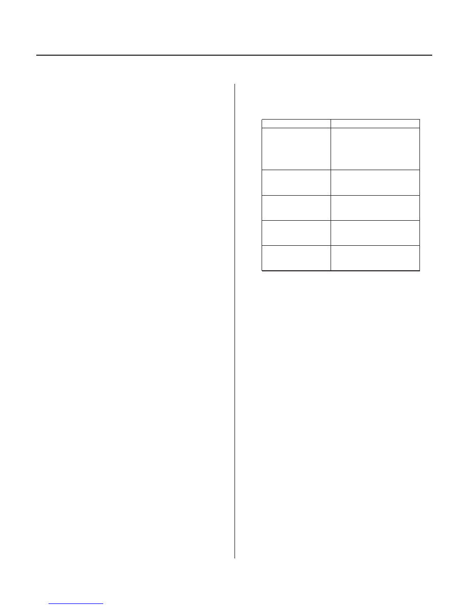
7. If the measurements are out of the service limit,

problems and probable causes are listed in the
table:


Stall speed rpm
high in the D, 2, 1,
and R positions

Low fluid level
ATF pump output low
Clogged ATF strainer
Regulator valve stuck
Slipping clutch

Stall speed rpm
high in the 1
position

Slippage of 1st clutch
1st gear one-way
clutch defective

Stall speed rpm
high in the 2
position

Slippage of 2nd clutch

Stall speed rpm
high in the R
position

Slippage of 5th clutch

Stall speed low in
the D, 2, 1, and R
positions

Engine output low
Torque converter one-
way clutch slipping

03/07/29 09:40:12 61S0X050_140_0357

*01

*02

*03

S0X4AA1E10410800000FEAT00

Special Tools Required

14-355

Pressure Test

A/T OIL PRESSURE GAUGE SET W/PANEL
07406-0020400 or 07406-0020401

A/T PRESSURE
HOSE, 2,210 mm
07MAJ-PY4011A
(4 Required)

A/T PRESSURE
HOSE ADAPTER
07MAJ-PY40120
(4 Required)

B

A

C

F

G

E

D

• A/T clutch pressure gauge set

07406-0020400 or 07406-0020401

• A/T pressure hose, 2,210 mm 07MAJ-PY4011A
• A/T pressure hose adapter 07MAJ-PY40120

1. Before testing, be sure the transmission fluid is

filled to the proper level.

2. Raise the vehicle, and make sure it is securely

supported.

3. Allow all four wheels to rotate freely.

4. Warm up the engine (the radiator fan comes on),

then stop it and connect a tachometer.

5. Connect the oil pressure gauges to the line

pressure inspection hole (A), 2nd clutch pressure
inspection hole (B), and 1st-hold clutch pressure
inspection hole (C). Do not allow dust or other
foreign particles to enter the holes while
connecting the gauges.

6. Connect the oil pressure gauges to the 1st clutch

pressure inspection hole (D), 3rd clutch pressure
inspection hole (E), 4th clutch pressure inspection
hole (F), and 5th clutch pressure inspection hole (G).

(cont’d)

03/07/29 09:40:12 61S0X050_140_0358


Pressure

Fluid Pressure

Standard

Service Limit

Pressure

Fluid Pressure

Standard

Service Limit

Problem

Probable causes

Torque:

18 N·m (1.8 kgf·m,13 lbf·ft)

14-356

Automatic Transmission

Pressure Test (cont’d)

7. Start the engine, and run it at 2,000 rpm in the P or

N position.

8. Measure line pressure at the line pressure

inspection hole (A).

NOTE: Higher pressure may be indicated if
measurements are made in shift lever position
other than N or P.

Line (A)

900

960 kPa

(9.2

9.8 kgf/cm ,

130

140 psi)

850 kPa
(8.7 kgf/cm ,
120 psi)

9. Shift to the 1 position, and measure 1st clutch

pressure at the 1st clutch pressure inspection hole
(G) and 1st-hold clutch pressure at the 1st-hold
clutch pressure inspection hole (C).

10. Shift to the 2 position, and measure 2nd clutch

pressure at the 2nd clutch pressure inspection hole
(B).

11. Shift to the P position, then press the brake pedal

and hold it.

12. Shift to the 2 position, and release the brake pedal

(the transmission should be in 2nd gear).

13. Press the accelerator very slowly to increase

engine speed to 2,000 rpm gradually over 10
seconds, then hold it at 2,000 rpm.

14. Hold in the 2 position at 2,000 rpm, shift into N for 1

second, then shift to the D3 position (the
transmission will shift to 3rd gear), and measure
3rd clutch pressure at the 3rd clutch pressure
inspection hole (D).

15. Shift to the D position, and measure 4th clutch

pressure at the 4th clutch pressure inspection hole
(E), then in about 15 seconds, the transmission will
shift to 5th gear.

16. Measure 5th clutch pressure at the 5th clutch

pressure inspection hole (F).

17. Bring the engine back to an idle, then apply the

brake to stop the wheels from rotating.

18. Shift to the R position. Raise the engine rpm to

2,000 rpm, and measure the reverse clutch
pressure at the 5th clutch pressure inspection hole
(F).

1st-hold
clutch (C)

760

830 kPa

(7.7

8.5 kgf/cm ,

110

120 psi)

710 kPa
(7.2 kgf/cm ,
100 psi)

1st clutch
(G)

890

970 kPa

(9.1

9.9 kgf/cm ,

130

140 psi)

840 kPa
(8.6 kgf/cm ,
120 psi)

2nd clutch
(B)
3rd clutch
(D)
4th clutch
(E)
5th clutch
(F)

19. If the measurements are out of service limit,

problems and probable causes are listed in the
table below:


No or low line
pressure

Torque converter
ATF pump
Regulator valve
Torque converter
check valve

No or low 1st clutch
pressure

1st clutch
O-rings

No or low 2nd clutch
pressure

2nd clutch
O-rings

No or low 3rd clutch
pressure

3rd clutch
O-rings

No or low 4th clutch
pressure

4th clutch
O-rings

No or low 5th clutch
pressure

5th clutch
O-rings

No or low 5th clutch
pressure in the R
position

Servo valve
5th clutch
O-rings

20. Install the sealing bolts with the new sealing

washers, and tighten the bolts to the specified
torque. Do not reuse old sealing washers.

2

2

2

2

2

2

03/07/29 09:40:13 61S0X050_140_0359

01

S0X4AA1E10410659548FEAT01

01

S0X4AA1E10410659548KBAT00

Standard: 12

25

14-357

14-357

Torque Converter Clutch Solenoid
Valve Test

Torque Converter Clutch Solenoid
Valve Replacement

6 x 1.0 mm
12 N·m (1.2 kgf·m, 8.7 lbf·ft)

A

B

1. Disconnect the connector from the torque

converter clutch solenoid valve.

2. Measure torque converter clutch solenoid valve

resistance at the solenoid valve connector (black).

3. Replace torque converter clutch solenoid valve if

the resistance is out of standard.

4. If the resistance is within the standard, connect the

No. 2 terminal of the torque converter clutch
solenoid valve connector to the battery positive
terminal, and connect the No. 1 terminal to the
battery negative terminal. A clicking sound should
be heard.
Replace torque converter clutch solenoid valve if
no clicking sound is heard.

1. Remove the mounting bolt and torque converter

clutch solenoid valve.

2. Install a new torque converter clutch solenoid valve

(A) with new O-rings (B). When installing the
solenoid valve, do not allow dust or other foreign
particles to enter the transmission.

3. Check the connector for rust, dirt, or oil, then

reconnect it.

03/07/29 09:40:13 61S0X050_140_0360


Content   ..  238  239  240  241   ..