Honda Odyssey 2004. Manual - part 222
*05
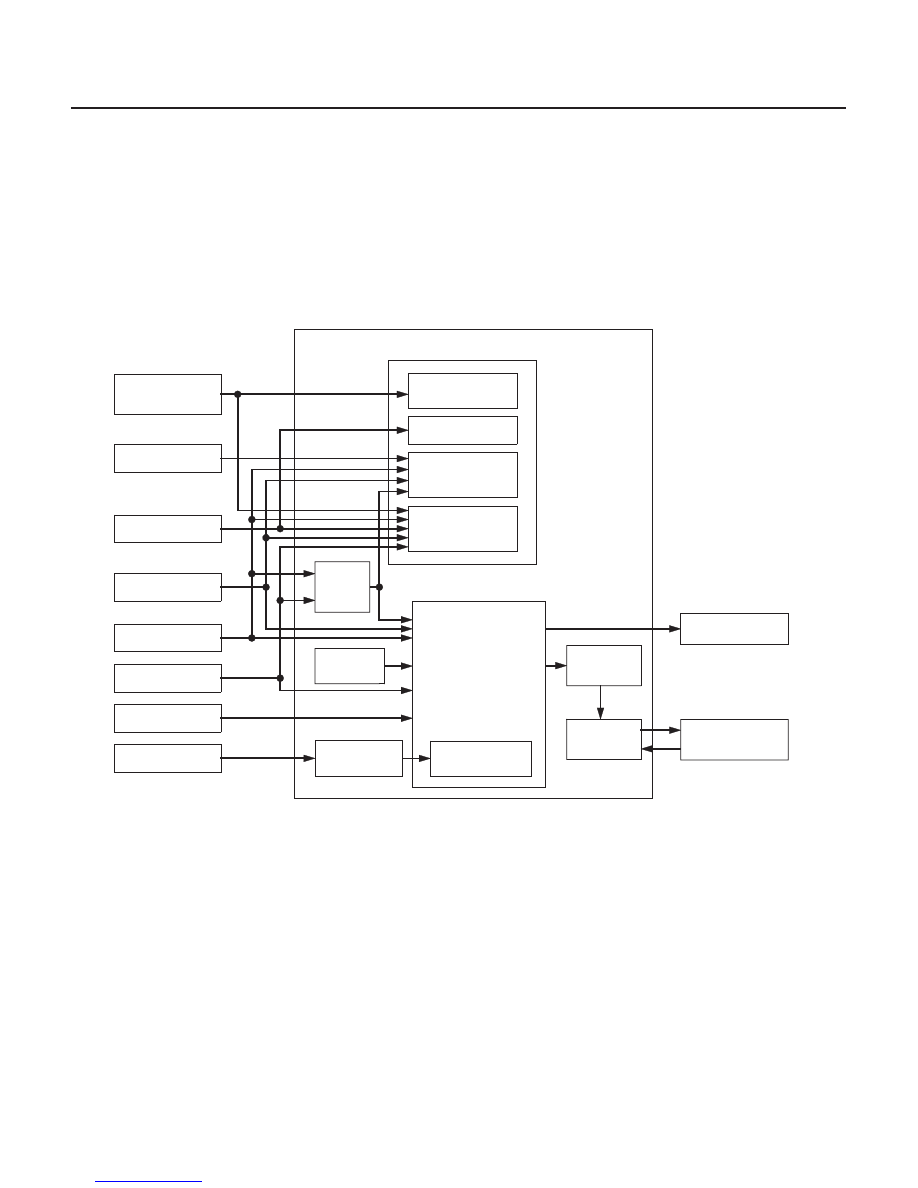
Electronic Control System (cont’d)
Lock-up Control
14-282
Automatic Transmission
System Description (cont’d)
PCM
Engine RPM Signal
Engine Coolant
Temperature
Sensor Signal
Barometric Pressure
Sensor Signal
Transmission Range
Switch Signal
Lock-up condition
learning Control
ATF Temperature
Sensor Signal
A/T Clutch Pressure
Control Solenoid
Valve C
Throttle Position
Sensor Signal
Engine Coolant
Temperature
control
Actual
Driving
Shift
Position
Correction of
ATF temperature
sensor data
Master Target
of Controlling
Current
Current
feedback
Driving shift
position
information
Shifting position
control
Gradient control
by magnitude
Fail-safe control
Lock-up Control
• Lock-up ON/OFF control
• Lock-up condition
control
Input Shaft (Mainshaft)
Speed Sensor Signal
Torque Converter
Clutch Solenoid Valve
Output Shaft (Countershaft)
Speed Sensor Signal
The torque converter clutch solenoid valve controls the hydraulic pressure to switch the lock-up shift valve and lock-up
ON and OFF. The PCM actuates the torque converter clutch solenoid valve and the A/T clutch pressure control
solenoid valve C to control the torque converter clutch lock-up on. When the torque converter clutch solenoid valve is
ON, the condition of the lock-up starts. The A/T clutch pressure control solenoid valve C regulates and applies the
hydraulic pressure to the lock-up control valve to control the amount of the lock-up.
The lock-up mechanism operates in 3rd, 4th, and 5th gears in the D position, and 3rd gear in the D3 position.
03/07/29 09:37:15 61S0X050_140_0285