Honda Odyssey 2004. Manual - part 221
*03
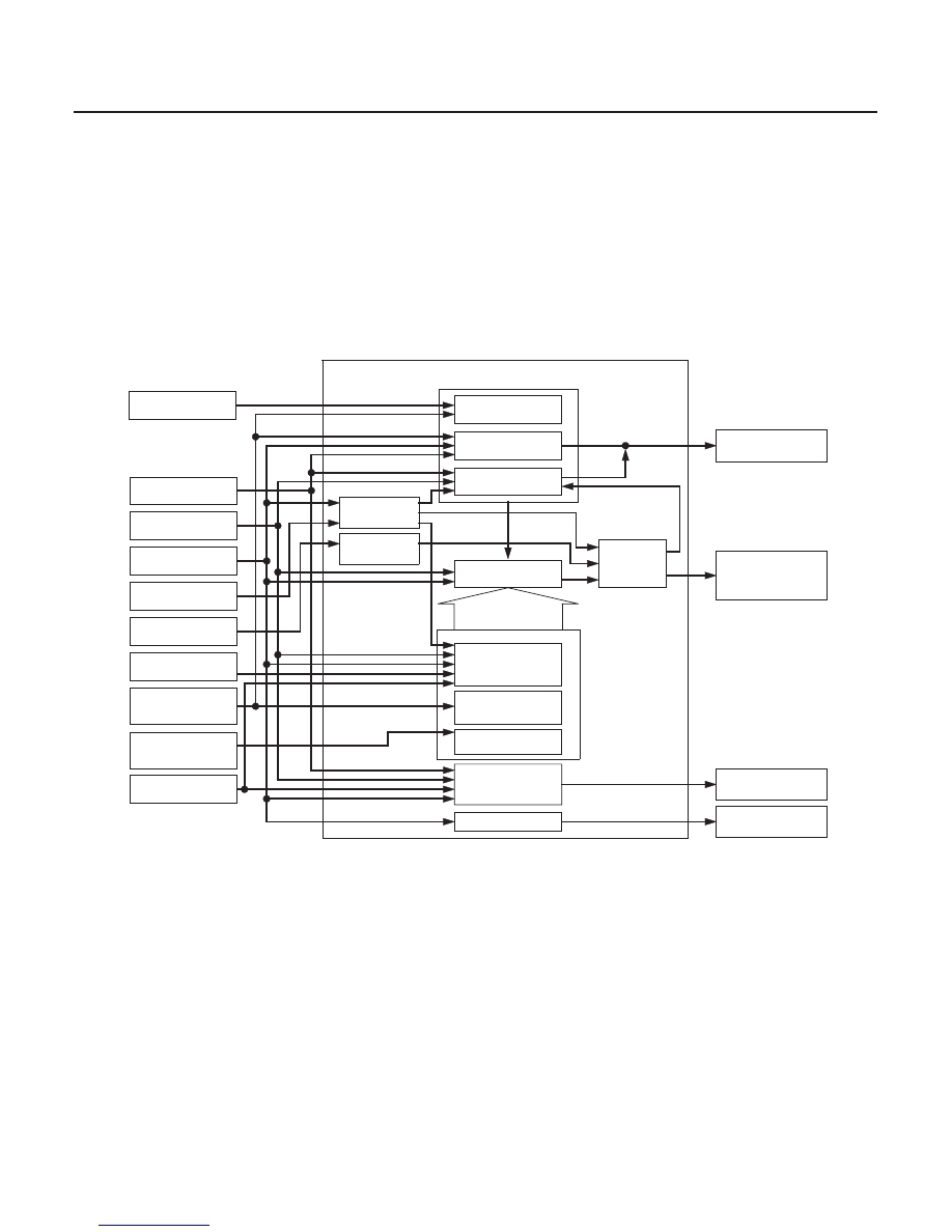
Electronic Control System
Shift Control
14-278
Automatic Transmission
System Description (cont’d)
PCM
Engine RPM Signal
Throttle Position
Sensor Signal
Engine Coolant
Temperature
Sensor Signal
Barometric Pressure
Sensor Signal
Transmission Range
Switch Signal
Brake Pedal Position
Switch Signal
A/T Gear Position
Indicator D Indicator
Vehicle Speed Signal
Shift Lock Solenoid
ATF Temperature
Sensor Signal
Cruise Control
Downshift Request
Signal
Actual Driving
Shift Position
ATF
Temperature
Engine RPM Control
Shift Position
Control
Fail-safe Control
Comparison
with
Signals
Master Target of
Shifting Position
Correction of Data
Selection of Shifting
mode
Grade Logic Control
Calculation of
gradient
Correction of engine
coolant temperature
sensor signal data
Correction of cruise
control signal data
Judgment of
Controlling Area
Frequency Divider
Input Shaft (Mainshaft)
Speed Sensor Signal
Output Shaft (Countershaft)
Speed Sensor Signal
Shift Solenoid Valve A
Shift Solenoid Valve B
Shift Solenoid Valve C
The PCM instantly determines which gear should be selected by various signals sent from sensors and switches, and
it actuates the shift solenoid valves A, B, and C to control shifting.
Also, as grade logic control system has been adopted to control shifting in the D and D3 positions. The PCM compares
actual driving conditions with memorized driving conditions, based on the input from the throttle position sensor, the
engine coolant temperature sensor, the barometric pressure sensor, the brake pedal position switch signal, and the
shift lever position signal, to control shifting while the vehicle is ascending or descending a slope.
03/07/29 09:37:13 61S0X050_140_0281