Honda Odyssey 2004. Manual - part 209
*04
*05
01
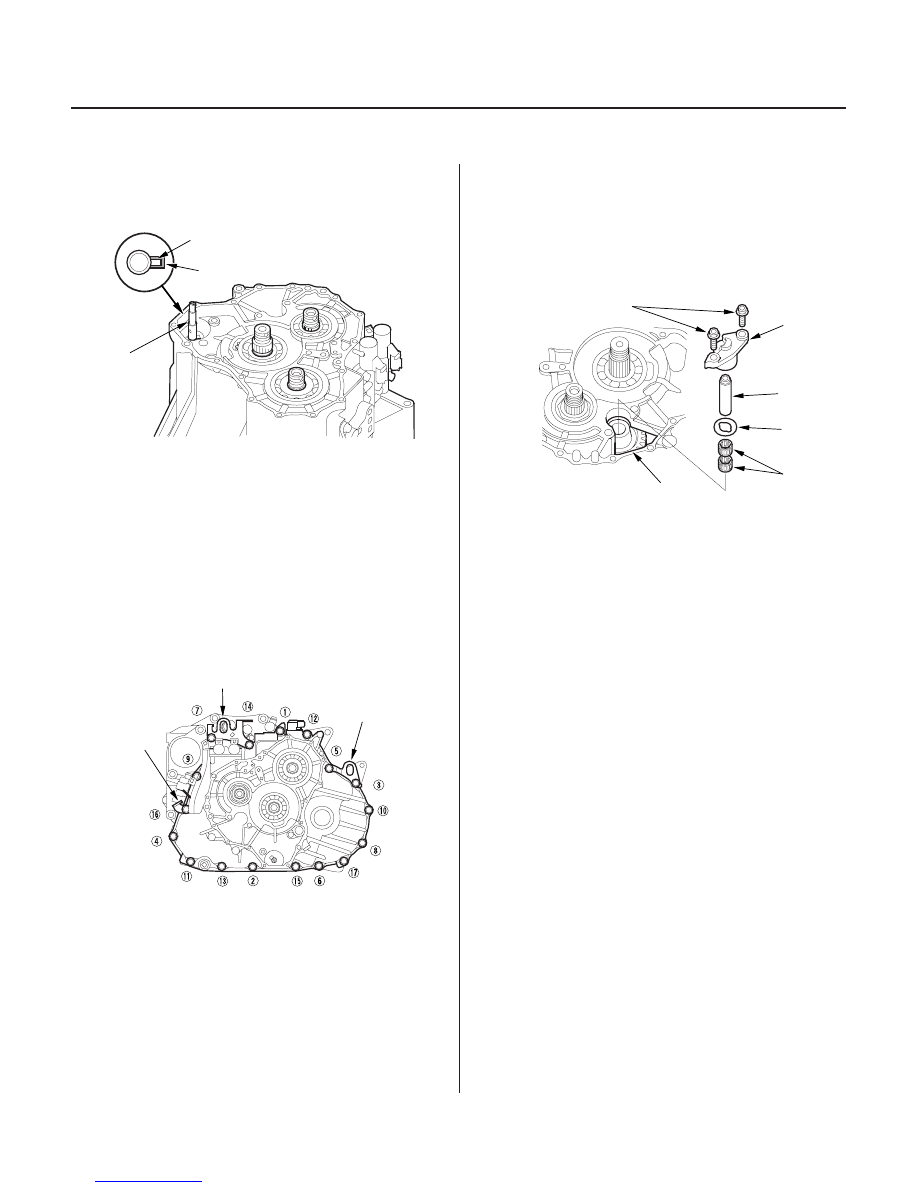
Torque:
44 N·m (4.5 kgf·m, 33 lbf·ft)
14-230
Transmission Housing
Shaft Assembly and Housing Installation (cont’d)
A
C
B
A
C
B
8 x 1.25 mm
26 N·m (2.7 kgf·m, 20 lbf·ft)
E
B
C
A
D
7. Align the spring pin (A) on the control shaft (B) with
the transmission housing groove (C) by turning the
control shaft.
8. Install three dowel pins and a new gasket on the
torque converter housing.
9. Place the transmission housing on the torque
converter housing, then install the transmission
housing mounting bolts along with the harness
clamp bracket (A), transmission hanger (B), and
transmission hanger/harness clamp bracket (C).
Tighten the bolts in two or more steps in the
sequence shown.
10. Engage the reverse idler gear with the countershaft
reverse gear and the mainshaft reverse gear. Then
install the needle bearings (A), reverse idler gear
shaft (B), and thrust washer (C) in the reverse idler
gear (D), and install the reverse idler gear shaft
holder (E) on the transmission housing.
03/07/29 09:35:44 61S0X050_140_0233