Honda Odyssey 2004. Manual - part 201


  Index      Honda     Honda Odyssey 2004 - service repair manual 2004 year


Search            


Content   ..  199  200  201  202   ..


Honda Odyssey 2004. Manual - part 201


01

S0X4AA0E10480139301MEAT00

14-198

Valve Body

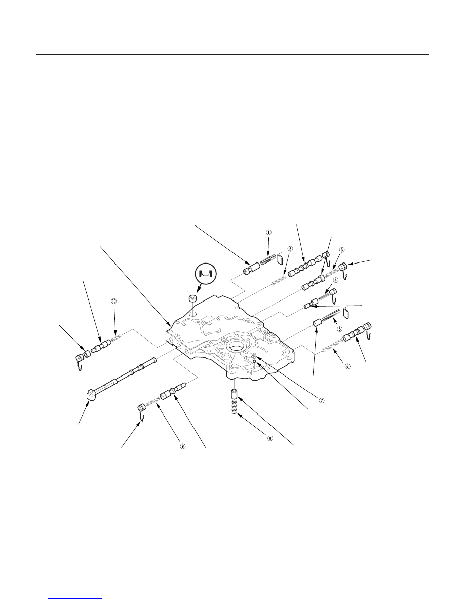
Main Valve Body Disassembly, Inspection, and Reassembly

SHIFT VALVE C

SHIFT VALVE D

VALVE CAP

SHIFT VALVE E

LOCK-UP SHIFT
VALVE

RELIEF VALVE

COOLER CHECK VALVE (BALL)

TORQUE CONVERTER CHECK VALVE

SERVO CONTROL VALVE

VALVE CAP CLIP

MANUAL VALVE

VALVE
SLEEVE

REVERSE CPC
VALVE

MAIN VALVE BODY

FILTER

MODULATOR VALVE

1. Clean all parts thoroughly in solvent or carburetor cleaner, and dry them with compressed air. Blow out all

passages.

2. Do not use a magnet to remove the check valve ball; it may magnetize the ball.

3. Check all valves for free movement. If any fail to slide freely, refer to Valve Body Repair (see page 14-196).

4. Replace the valve body as an assembly if any parts are worn or damaged.

5. Coat all parts with ATF during assembly.

6. Install the filter in the direction shown.

Inspect for scoring and
damage.

Install in this direction.

03/07/29 09:35:21 61S0X050_140_0201

*01

Sectional View

SPRING SPECIFICATIONS

No.

Spring

Standard (New)-Unit: mm (in.)

Wire Dia.

O.D.

Free Length

No. of Coils

14-199

FILTER

MAIN VALVE BODY

MANUAL VALVE

Modulator valve spring

1.6 (0.063)

10.4 (0.409)

33.5 (1.319)

9.8

Shift valve C spring

0.8 (0.031)

6.6 (0.260)

49.1 (1.933)

21.7

Shift valve D spring

0.7 (0.028)

6.6 (0.260)

35.7 (1.406)

17.2

Shift valve E spring

0.7 (0.028)

6.1 (0.240)

17.8 (0.701)

7.9

Relief valve spring

1.1 (0.043)

8.6 (0.339)

30.1 (1.185)

10.7

Lock-up shift valve spring

0.9 (0.035)

7.6 (0.299)

63.0 (2.480)

22.4

Cooler check valve spring

0.6 (0.024)

5.8 (0.228)

14.5 (0.571)

6.8

Torque converter check valve

1.2 (0.047)

8.6 (0.339)

34.4 (1.354)

11.7

Servo control valve spring

0.7 (0.028)

6.6 (0.260)

35.7 (1.406)

17.2

Reverse CPC valve spring

0.7 (0.028)

6.1 (0.240)

17.8 (0.701)

7.9

Sectional View

03/07/29 09:35:21 61S0X050_140_0202

*01

*02

*03

S0X4AA0E10480113021MAAT00

ATF Pump Gears Side (Radial) Clearance:
Standard (New):
ATF Pump Drive Gear
0.210

0.265 mm (0.0083

0.00104 in.)

ATF Pump Driven Gear
0.070

0.125 mm (0.0028

0.0050 in.)

ATF Pump Drive/Driven Gear Thrust (Axial)
Clearance:
Standard (New): 0.03

0.05 mm (0.001

0.002 in.)

Service Limit:

0.07 mm (0.003 in.)

14-200

Valve Body

ATF Pump Inspection

A

B

C

D

A

B

B

D

A

C

1. Install the ATF pump drive gear (A), driven gear (B),

and ATF pump driven gear shaft (C) in the main
valve body (D). Lubricate all parts with ATF, and
install the ATF pump driven gear with its grooved
and chamfered side facing up.

2. Measure the side clearance of the ATF pump drive

gear (A) and driven gear (B).

3. Remove the ATF pump driven gear shaft. Measure

the thrust clearance between the ATF pump driven
gear (A) and the valve body (B) with a straight edge
(C) and a feeler gauge (D).

03/07/29 09:35:22 61S0X050_140_0203

01

S0X4AA0E10480150701MEAT00

SPRING SPECIFICATIONS

No.

Spring

Standard (New)-Unit: mm (in.)

Wire Dia.

O.D.

Free Length

No. of Coils

14-201

Regulator Valve Body Disassembly, Inspection, and Reassembly

REGULATOR SPRING CAP

REGULATOR VALVE

STOP BOLT
6 x 1.0 mm
12 N·m (1.2 kgf·m, 8.7 lbf·ft)

REGULATOR VALVE BODY

FILTER

LOCK-UP CONTROL VALVE

VALVE SLEEVE

VALVE CAP CLIP

LOCK-UP TIMING VALVE

VALVE CAP

1. Clean all parts thoroughly in solvent or carburetor cleaner, and dry them with compressed air. Blow out all

passages.

2. Check all valves for free movement. If any fail to slide freely, refer to Valve Body Repair (see page 14-196).

3. Replace the valve body as an assembly if any parts are worn or damaged.

4. Hold the regulator spring cap in place while removing the stop bolt. The regulator spring cap is spring loaded.

Once the stop bolt is removed, release the spring cap slowly so it does not pop out.

5. Reassembly is the reverse of disassembly. Install the filter in the direction shown.

6. Coat all parts with ATF during reassembly.

7. Align the hole in the regulator spring cap with the hole in the valve body, then press the spring cap into the valve

body, and tighten the stop bolt.

Stator reaction spring

5.5 (0.217)

37.4 (1.472)

30.3 (1.193)

2.12

Regulator valve spring A

1.9 (0.075)

14.7 (0.579)

77.4 (3.047)

15.2

Regulator valve spring B

1.6 (0.063)

9.2 (0.362)

44.0 (1.732)

12.5

Lock-up control valve spring

0.8 (0.031)

6.6 (0.260)

44.3 (1.744)

25.5

Lock-up timing valve spring

0.65 (0.026)

6.6 (0.260)

34.8 (1.370)

15.6

Inspect for scoring and
damage.

Install in this direction.

03/07/29 09:35:23 61S0X050_140_0204


Content   ..  199  200  201  202   ..