Honda Odyssey 2004. Manual - part 200


  Index      Honda     Honda Odyssey 2004 - service repair manual 2004 year


Search            


Content   ..  198  199  200  201   ..


Honda Odyssey 2004. Manual - part 200


*01

S0X4AA0E10480139301KAAT00
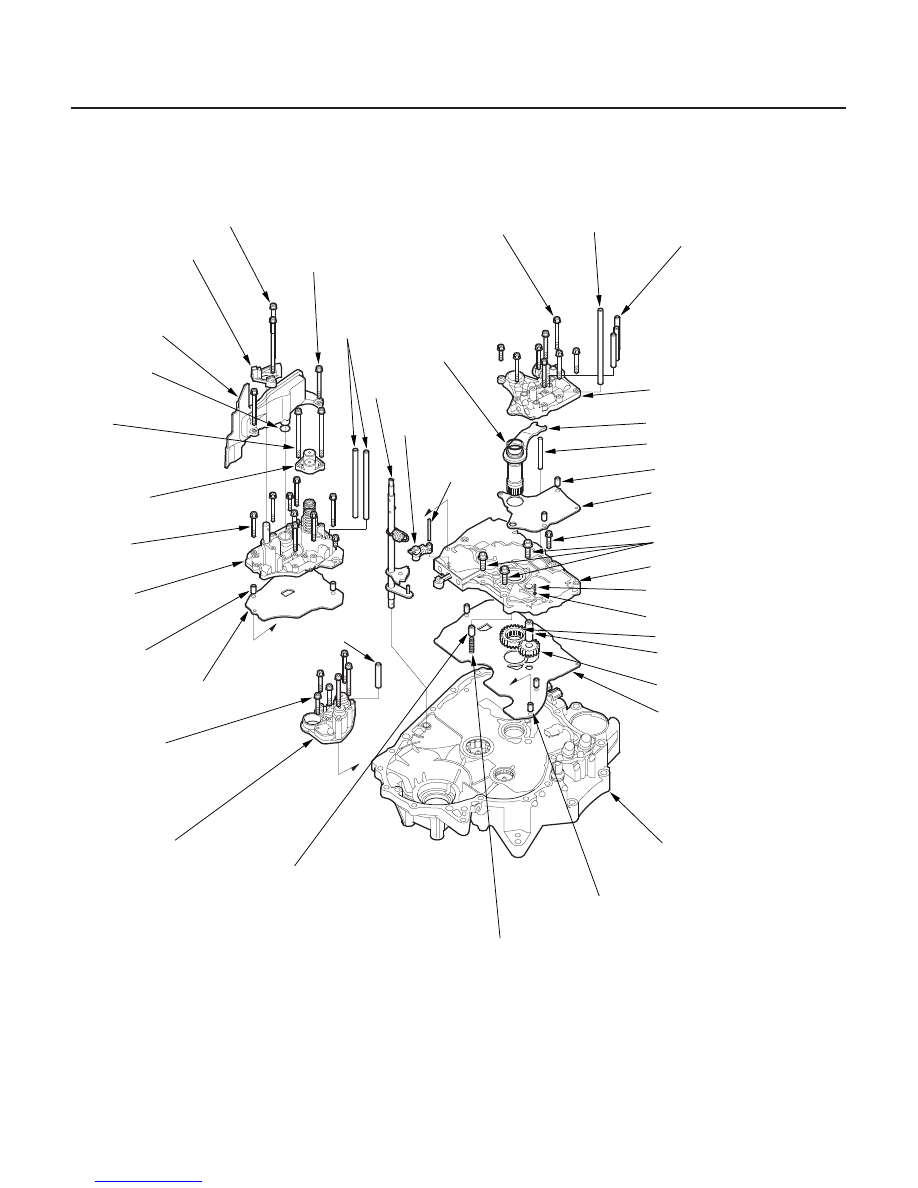
Exploded View

14-194

Valve Body

Valve Body and ATF Strainer Removal

6 x 1.0 mm,
Eight Bolts

ATF FEED PIPE,
8 x 198 mm

ATF FEED PIPES,
8 x 85 mm, Three Pipes

STATOR SHAFT

STATOR SHAFT STOP

DOWEL PINS, Two Pins

REGULATOR
SEPARATOR PLATE

6 x 1.0 mm, One Bolt

8 x 1.25 mm, Three Bolts

MAIN VALVE BODY

COOLER CHECK VALVE
SPRING

COOLER CHECK VALVE

ATF PUMP DRIVE GEAR

ATF PUMP DRIVEN GEAR

MAIN SEPARATOR PLATE

TORQUE CONVERTER
CHECK VALVE

DOWEL PINS, Three Pins

TORQUE CONVERTER
CHECK VALVE SPRING

TORQUE CONVERTER
HOUSING

ACCUMULATOR
BODY

6 x 1.0 mm,
Six Bolts

SERVO SEPARATOR
PALATE

DOWEL PINS,
Two Pins

SERVO BODY

6 x 1.0 mm,
Nine Bolts

6 x 1.0 mm,
Two Bolts

O-RING

ATF STRAINER

SERVO DETENT
BASE

6 x 1.0 mm,
Two Bolts

6 x 1.0 mm,
Two Bolts

ACCUMULATOR
COVER

ATF FEED
PIPES,
Two Pipes

O-RING

DETENT
ARM SHAFT

DETENT
ARM

CONTROL
SHAFT

ATF FEED
PIPE

ATF PUMP DRIVEN GEAR
SHAFT

REGULATOR
VALVE BODY

Replace.

Replace.

03/07/29 09:34:23 61S0X050_140_0197

02

14-195

B

A

NOTE: Refer to the Exploded View as needed during the
following procedure.

1. Remove the ATF feed pipes from the regulator

valve body, servo body and accumulator body.

2. Remove the servo detent base (two bolts).

3. Remove the ATF strainer (two bolts).

4. Remove the accumulator cover (two bolts).

5. Remove the bolts securing the servo body (nine

bolts), then remove the servo body, servo
separator plate, and dowel pins (two).

6. Remove the accumulator body (six bolts).

7. Remove the regulator valve body (eight bolts).

8. Remove the stator shaft and stator shaft stop.

9. Remove the regulator separator plate and dowel

pins (two).

10. Unhook the detent spring from the detent arm, then

remove the detent arm shaft, detent arm, and
control shaft.

11. Remove the cooler check valve spring and cooler

check valve (steel ball).

12. Remove the main valve body (four bolts).

13. Remove the torque converter check valve and

spring.

14. Remove the ATF pump driven gear shaft, then

remove the ATF pump gears.

15. Remove the main separator plate and dowel pins

(three).

16. Clean the inlet opening (A) of the ATF strainer (B)

thoroughly with compressed air, then check that it
is in good condition, and the inlet opening is not
clogged.

17. Test the ATF strainer by pouring clean ATF through

the inlet opening, and replace it if it is clogged or
damaged.

03/07/29 09:34:24 61S0X050_140_0198

01

02

S0X4AA0E10480139301LBAT00

14-196

Valve Body

Valve Body Repair

NOTE: This repair is only necessary if one or more of
the valves in a valve body do not slide smoothly in their
bores. Use this procedure to free the valves.

1. Soak a sheet of

600 abrasive paper in ATF for

about 30 minutes.

2. Carefully tap the valve body so the sticking valve

drops out of its bore. It may be necessary to use a
small screwdriver to pry the valve free. Be careful
not to scratch the bore with the screwdriver.

3. Inspect the valve for any scuff marks. Use the ATF-

soaked

600 paper to polish off any burrs that are

on the valve, then wash the valve in solvent and
dry it with compressed air.

4. Roll up half a sheet of ATF-soaked

600 paper and

insert it in the valve bore of the sticking valve.
Twist the paper slightly, so that it unrolls and fits
the bore tightly, then polish the bore by twisting the
paper as you push it in and out.

NOTE: The valve body is aluminum and doesn’t
require much polishing to remove any burrs.

5. Remove the

600 paper. Thoroughly wash the

entire valve body in solvent, then dry it with
compressed air.

6. Coat the valve with ATF, then drop it into its bore. It

should drop to the bottom of the bore under its
own weight. If not, repeat steps 4 and 5, then retest.
If the valve still sticks, replace the valve body.

7. Remove the valve, and thoroughly clean it and the

valve body with solvent. Dry all parts with
compressed air, then reassemble using ATF as a
lubricant.

03/07/29 09:34:24 61S0X050_140_0199

01

02

S0X4AA0E10480139301LDAT00

14-197

Valve Body Valve Reassembly

A

B

C

1. Coat all parts with ATF before assembly.

2. Install the valves and springs in the sequence

shown for the main valve body (see page 14-198),
regulator valve body (see page 14-201), and servo
body (see page 14-202). Refer to the following
valve cap illustrations, and install each valve cap so
the end shown facing up will be facing the outside
of the valve body.

3. Install all the springs and seats. Insert the spring (A)

in the valve, then install the valve in the valve body
(B). Push the spring in with a screwdriver, then
install the spring seat (C).

03/07/29 09:34:25 61S0X050_140_0200


Content   ..  198  199  200  201   ..