Honda Odyssey 2004. Manual - part 189
11
12
13
14
14-150
Automatic Transmission
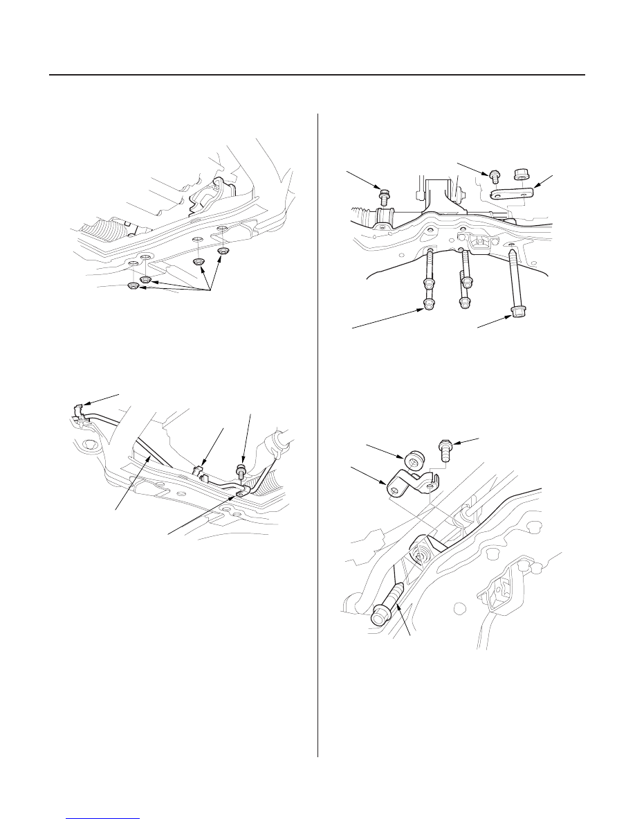
Transmission Installation (cont’d)
10 x 1.25 mm
38 N·m (3.9 kgf·m,
28 lbf·ft)
C
A
B
B
6 x 1.0 mm
9.8 N·m
(1.0 kgf·m,
7.2 lbf·ft)
C
A
10 x 1.25 mm
38 N·m (3.9 kgf·m,
28 lbf·ft)
B
10 x 1.25 mm
58 N·m (5.9 kgf·m,
43 lbf·ft)
B
10 x 1.25 mm
39 N·m (4.0 kgf·m,
29 lbf·ft)
10 x 1.25 mm
59 N·m (6.0 kgf·m,
43 lbf·ft)
B
10 x 1.25 mm
58 N·m (5.9 kgf·m, 43 lbf·ft)
C
A
10 x 1.25 mm
59 N·m (6.0 kgf·m,
43 lbf·ft)
18. Install the transmission lower mount nuts.
19. Install the power steering fluid pipe (A) on the
clamps (B), and install the power steering fluid pipe
bracket (C).
20. Install the rear mount mounting bolts (A).
21. Install the steering gearbox mounting bolts (B) and
the stiffener (C).
22. Install the stiffener (A) and the steering gearbox
mounting bolt (B) with nut (C).
03/07/29 09:33:48 61S0X050_140_0153