Honda Odyssey 2004. Manual - part 172
−
−
−
−
03
04
YES
NO
YES
NO
14-82
Automatic Transmission
DTC Troubleshooting (cont’d)
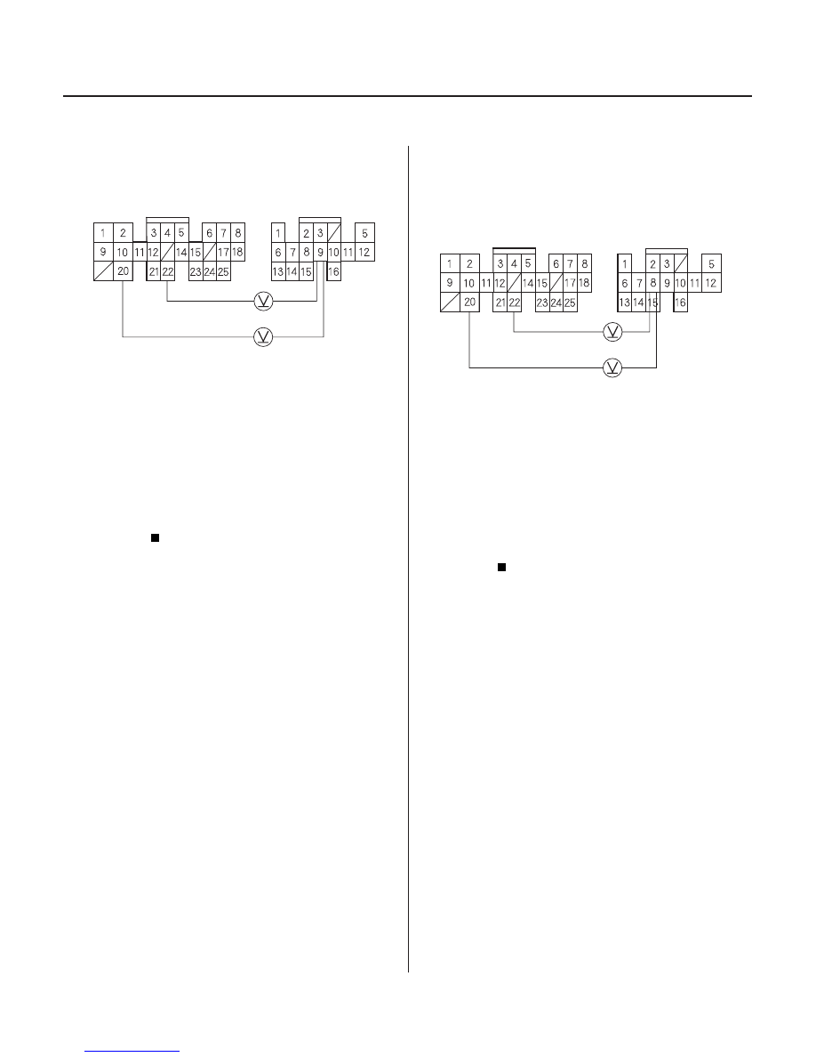
PCM CONNECTORS
B (25P)
ATP D4 (YEL)
LG1 (BRN/BLK)
LG2 (BRN/BLK)
D (16P)
PCM CONNECTORS
B (25P)
ATP D3
(PNK)
LG1 (BRN/BLK)
LG2 (BRN/BLK)
D (16P)
11. Measure the voltage between the D9 and B20 or
B22 terminals.
Go to step 12.
Check for a short in the wire between the D9
terminal and the A/T gear position switch or A/T
gear position indicator. If wire is OK, check for
loose terminal fit in the PCM connectors. If
necessary, substitute a known-good PCM and
recheck.
12. Shift to all positions other than D3.
13. Measure the voltage between the D8 and B20 or
B22 terminals.
Go to step 14.
Check for a short in the wire between the D8
terminal and the A/T gear position switch or A/T
gear position indicator. If wires are OK, check for
loose terminal fit in the PCM connectors. If
necessary, substitute a known-good PCM and
recheck.
Wire side of female terminals
Wire side of female terminals
Is ther e about 5 V ?
Is ther e batter y voltage?
03/07/29 09:31:06 61S0X050_140_0085