Honda Odyssey 2004. Manual - part 171
−
−
−
−
−
−
−
03
*02
04
YES
NO
YES
NO
YES
NO
14-78
Automatic Transmission
DTC Troubleshooting (cont’d)
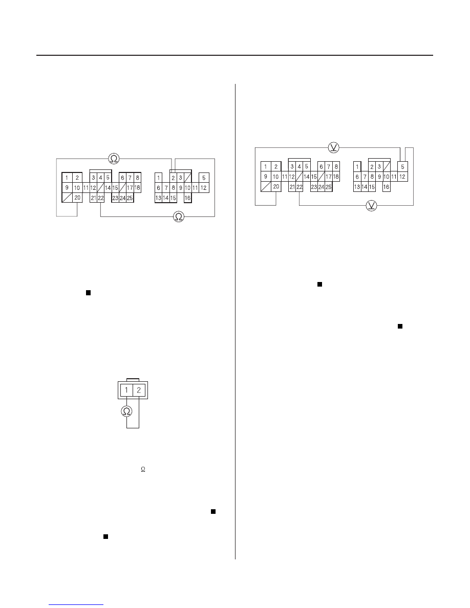
PCM CONNECTORS
B (25P)
LG1 (BRN/BLK)
LG2 (BRN/BLK)
D (16P)
SH B (GRN/WHT)
SHIFT CONTROL SOLENOID
VALVE B CONNECTOR
PCM CONNECTORS
B (25P)
LG1 (BRN/BLK)
LG2 (BRN/BLK)
D (16P)
VB SOL (BLK/YEL)
8. Disconnect the 2P connector from the shift control
solenoid valve B.
9. Check for continuity between the D2 and B20 or
B22 terminals.
Repair short to ground in the wire between
the D2 terminal and the shift control solenoid
valve B.
Go to step 10.
10. Measure shift control solenoid valve B resistance at
the solenoid valve connector.
Check for an open in the wires between the
D2 terminal and the shift control solenoid valve B
and between the No. 1 terminal of the shift control
solenoid valve B connector and ground (G101).
Replace the shift control solenoid valve B (see
page 14-131).
11. Turn the ignition switch ON (II).
12. Measure the voltage between the D5 and B20 or
B22 terminals.
Check for loose terminal fit in the PCM
connectors. If necessary, substitute a known-good
PCM and recheck.
Check for blown No. 6 (15A) fuse in the
driver’s under-dash fuse/relay box. If the fuse is OK,
repair open in the wire between the D5 terminal
and the driver’s under-dash fuse/relay box.
Wire side of female terminals
Terminal side of male terminals
Wire side of female terminals
Is ther e continuity?
Is the r esistance 12
25
?
Is ther e batter y voltage?
03/07/29 09:31:04 61S0X050_140_0081