Honda Odyssey 2004. Manual - part 167


  Index      Honda     Honda Odyssey 2004 - service repair manual 2004 year


Search            


Content   ..  165  166  167  168   ..


Honda Odyssey 2004. Manual - part 167


*01

06

S0X4AA0E10474000000CAAT06

Lock-up System

General Operation

14-62

Automatic Transmission

System Description (cont’d)

MAINSHAFT

To ATF cooler

INLET

OUTLET

TURBINE

DAMPER SPRING

LOCK-UP PISTON

TORQUE CONVERTER
COVER

Power flow

The power flows by way of:

Engine

Drive plate

Torque converter cover

Lock-up piston

Damper spring

Turbine

Mainshaft

Power flow

Engine

Drive plate

Torque converter cover

Pump

Turbine

Mainshaft

MAINSHAFT

To ATF cooler

INLET

TURBINE

TORQUE CONVERTER
COVER

PUMP

The lock-up mechanism operates in D4 position (3rd and 4th), and D3 position (3rd). The pressurized fluid is drained
from the back of the torque converter through a fluid passage, causing the torque converter clutch piston to be held
against the torque converter cover. As this takes place, the mainshaft rotates at the same speed as the engine
crankshaft. Together with hydraulic control, the PCM optimizes the timing of the lock-up mechanism. When the torque
converter clutch solenoid valve activates, modulator pressure changes to switch lock-up ON and OFF. The lock-up
control valve and the lock-up timing valve control the amount of lock-up according to A/T clutch pressure control
solenoid valves A and B. The torque converter clutch solenoid valve is mounted on the torque converter housing, and
A/T clutch pressure control solenoid valves A and B are mounted on the transmission housing. They are controlled by
the PCM.

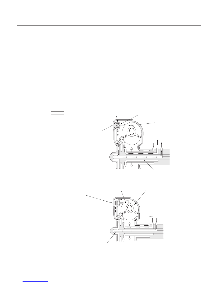
1. Operation (clutch on)

With the torque converter clutch on, fluid in the chamber between the torque converter clutch cover and the
torque converter clutch piston is drained off, and the converter fluid exerts pressure through the piston against
the torque converter cover. As a result, the converter turbine is locked to the converter cover. The effect is to
bypass the converter, placing the vehicle in direct drive.

2. Operation (clutch off)

With the torque converter clutch off, fluid flows in the reverse of CLUTCH ON. As a result, the torque converter
clutch piston moves away from the converter cover, and torque converter lock-up is released.

03/07/29 09:30:50 61S0X050_140_0065

23

No Lock-up

14-63

99

93

X

92

2

95

95’

95’

X

X

AX

MX

90

93

94

X

90

90’

91’

58

91

LA 94

91’

91

6

96

92

93

90

91

X

90

58

97

92

90

X

X

X

93

ATF COOLER

SECONDARY
SHAFT

LOCK-UP CONTROL
VALVE

REGULATOR VALVE

ATF PUMP

COUNTER-
SHAFT

LUBRICATION
CHECK VALVE

MAINSHAFT

COOLER
CHECK VALVE

TORQUE
CONVERTER
CHECK VALVE

TORQUE CONVERTER

LOCK-UP SHIFT
VALVE

LOCK-UP TIMING
VALVE

TORQUE CONVERTER
CLUTCH SOLENOID
VALVE

MODULATOR PRESSURE

RELIEF VALVE

The torque converter clutch solenoid valve is turned OFF by the PCM. The lock-up shift valve receives LC pressure (LA)
on the left side, and modulator pressure (6) on the right side. The lock-up shift valve is in the right side to uncover the
port leading torque converter pressure (92) to the left side of the torque converter. Torque converter pressure (92)
becomes torque converter pressure (94), and enters into the left side of the torque converter to disengage the torque
converter clutch. The torque converter clutch is OFF.

NOTE: When used, ‘‘left’’ or ‘‘right’’ indicates direction on the hydraulic circuit.

(cont’d)

03/07/29 09:30:51 61S0X050_140_0066

24

Lock-up System (cont’d)

Partial Lock-up

14-64

Automatic Transmission

System Description (cont’d)

99

93

X

92

2

95

95’

95’

X

X

AX

MX

90

93

94

X

90

90’

91’

58

91

LA 94

91’

91

6

96

92

93

90

91

X

90

58

97

92

90

X

X

X

93

X

ATF COOLER

SECONDARY
SHAFT

LOCK-UP CONTROL
VALVE

REGULATOR VALVE

ATF PUMP

COUNTER-
SHAFT

LUBRICATION
CHECK VALVE

MAINSHAFT

COOLER
CHECK VALVE

TORQUE
CONVERTER
CHECK VALVE

TORQUE CONVERTER

LOCK-UP SHIFT
VALVE

LOCK-UP TIMING
VALVE

TORQUE CONVERTER
CLUTCH SOLENOID
VALVE

MODULATOR PRESSURE

LS A or LS B PRESSURE

RELIEF VALVE

As the speed of the vehicle reaches the prescribed value, the torque converter clutch solenoid valve is turned ON by
the PCM to release LC pressure (LA) in the left side of the lock-up shift valve. The lock-up shift valve is moved to the
left side to switch the port leading torque converter pressure to the left side and right side of the torque converter.
Torque converter pressure (92) flows to the right side of the torque converter to engage the torque converter clutch.
The PCM also controls A/T clutch pressure control solenoid valves A and B, and LS A or LS B pressure is applied to the
lock-up control valve and the lock-up timing valve. The position of the lock-up control valve depends on torque
converter pressure and LS A or LS B pressure. When LS A or LS B pressure (58) is lower, torque converter pressure
(91) from the lock-up timing valve is lower. The torque converter clutch is engaged partially. LS A or LS B (58)
increases, and the lock-up timing valve is moved to the left side to uncover the port leading torque converter pressure
to high. The torque converter clutch is then engaged securely. Under this condition, the torque converter clutch is
engaged by pressure from the right side of the torque converter; this condition is partial lock-up.

NOTE: When used, ‘‘left’’ or ‘‘right’’ indicates direction on the hydraulic circuit.

03/07/29 09:30:52 61S0X050_140_0067

25

Full Lock-up

14-65

99

93

X

92

2

95

95’

95’

X

X

AX

MX

90

93

94

X

90

90’

91’

58

91

LA 94

91’

91

6

96

92

93

90

91

X

90

58

97

92

90

X

X

X

93

X

ATF COOLER

SECONDARY
SHAFT

LOCK-UP CONTROL
VALVE

REGULATOR VALVE

ATF PUMP

COUNTER-
SHAFT

LUBRICATION
CHECK VALVE

MAINSHAFT

COOLER
CHECK VALVE

TORQUE
CONVERTER
CHECK VALVE

TORQUE CONVERTER

LOCK-UP SHIFT
VALVE

LOCK-UP TIMING
VALVE

TORQUE CONVERTER
CLUTCH SOLENOID
VALVE

LS A or LS B PRESSURE

MODULATOR PRESSURE

When the vehicle speed further increases, the PCM controls A/T clutch pressure control solenoid valves A and B to
increase LS A or LS B pressure (58). The LS A or LS B pressure (58) is applied to the lock-up control valve and the lock-
up timing valve, and moves them to the left side. Under this condition, torque converter back pressure is released fully,
causing the torque converter clutch to be fully engaged.

NOTE: When used, ‘‘left’’ or ‘‘right’’ indicates direction on the hydraulic circuit.

03/07/29 09:30:52 61S0X050_140_0068


Content   ..  165  166  167  168   ..