Honda Odyssey 2004. Manual - part 159
*05
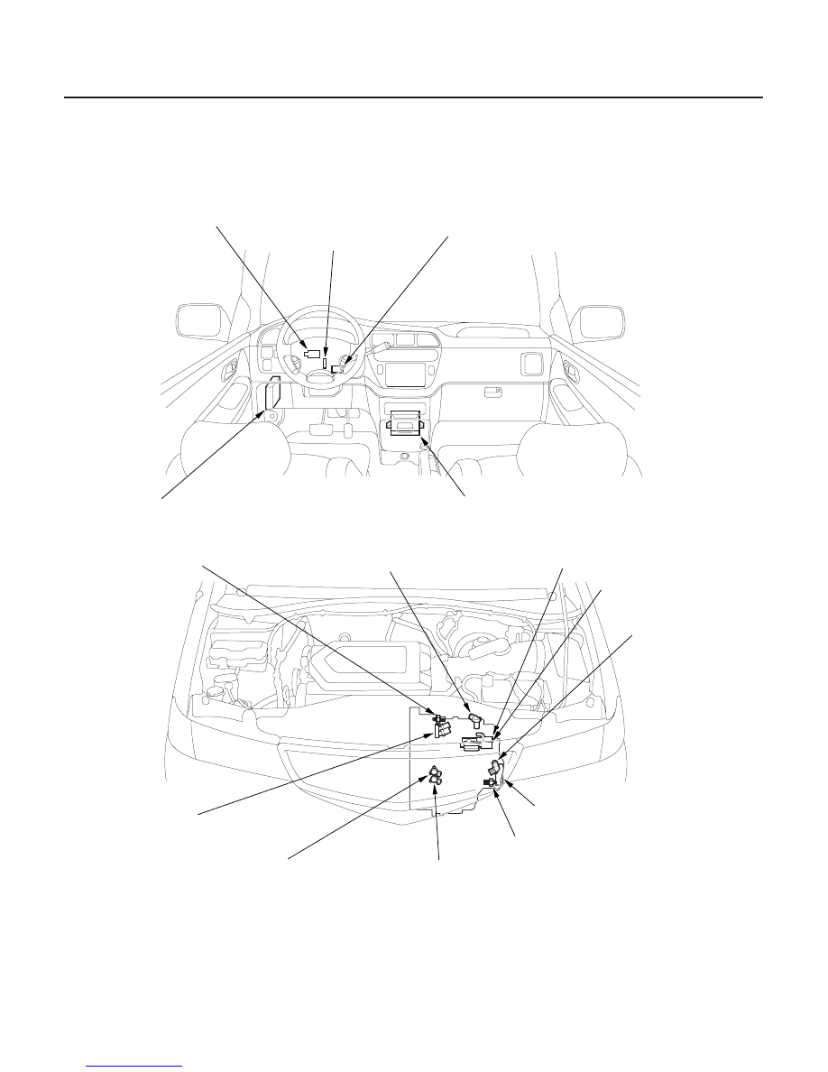
Electronic Control System (cont’d)
Electronic Controls Location
14-30
Automatic Transmission
System Description (cont’d)
KEY INTER LOCK SOLENOID
MULTIPLEX CONTROL
UNIT, DRIVER’S
SHIFT LOCK SOLENOID
PARK PIN SWITCH
POWERTRAIN CONTROL MODULE (PCM)
COUNTERSHAFT SPEED SENSOR
2ND CLUTCH PRESSURE SWITCH
TRANSMISSION RANGE SWITCH
MAINSHAFT SPEED
SENSOR
3RD CLUTCH PRESSURE
SWITCH
SHIFT SOLENOID
VALVE B
TORQUE CONVERTER CLUTCH
SOLENOID VALVE/
SHIFT SOLENOID VALVE A
A/T CLUTCH PRESSURE
CONTROL SOLENOID
VALVE B
SHIFT SOLENOID
VALVE C
A/T CLUTCH PRESSURE
CONTROL SOLENOID
VALVE A
03/07/29 09:29:24 61S0X050_140_0033