Honda Odyssey 2004. Manual - part 158
20
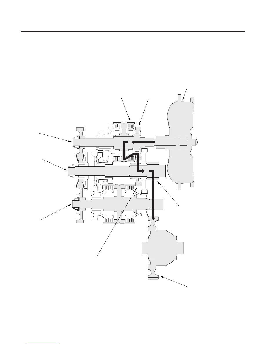
Power Flow (cont’d)
D4 or D3 Position in 3rd gear
14-26
Automatic Transmission
System Description (cont’d)
MAINSHAFT
COUNTERSHAFT
SECONDARY
SHAFT
TORQUE CONVERTER
FINAL DRIVEN GEAR
FINAL DRIVE GEAR
MAINSHAFT
3RD GEAR
3RD CLUTCH
COUNTERSHAFT
3RD GEAR
• Hydraulic pressure is applied to the 3rd clutch, then the 3rd clutch engages the mainshaft 3rd gear with the
mainshaft.
• The mainshaft 3rd gear drives the countershaft 3rd gear and the countershaft.
• Power is transmitted to the final drive gear, which in turn drives the final driven gear.
03/07/29 09:29:22 61S0X050_140_0029