Honda Odyssey 2004. Manual - part 143
−
−
−
−
−
−
*01
01
02
*02
YES
NO
YES
NO
EVAP Bypass Solenoid Valve Test
YES
NO
11-270
EVAP System
DTC Troubleshooting (cont’d)
EVAP PURGE CONTROL SOLENOID
VALVE 2P CONNECTOR
PCS (RED/YEL)
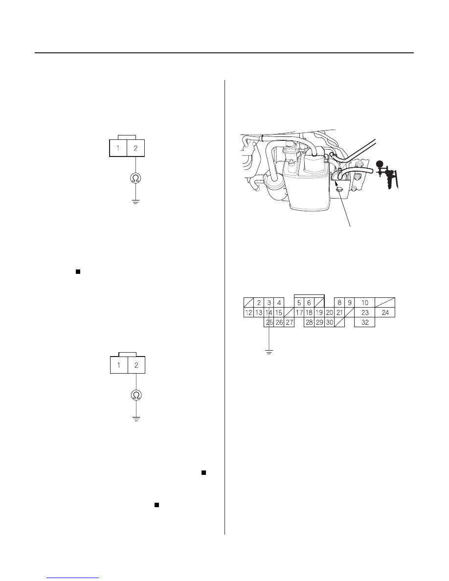
EVAP PURGE CONTROL SOLENOID
VALVE 2P CONNECTOR
PCS (RED/YEL)
A973X-041-
XXXXX
A
PCM CONNECTOR A (32P)
2WBS (BLU)
JUMPER WIRE
8. Check for continuity between EVAP purge control
solenoid valve 2P connector terminal No. 2 and
body ground.
Go to step 9.
Replace the EVAP purge control solenoid
valve.
9. Disconnect PCM connector A (32P).
10. Check for continuity between EVAP purge control
solenoid valve 2P connector terminal No. 2 and
body ground.
Repair short in the wire between the EVAP
purge control solenoid valve and the PCM (A6).
Substitute a known-good PCM and recheck
(see page 11-5). If the symptom/indication goes
away, replace the original PCM.
11. Disconnect both vacuum hoses from the EVAP two
way valve (A), and connect a vacuum pump to the
canister port on the two way valve.
12. Turn the bypass solenoid valve on with the HDS, or
connect PCM connector terminal A3 to body
ground with a jumper wire.
13. Turn the ignition switch ON (II).
14. Apply vacuum to the hose.
Go to step 15.
Go to step 20.
15. Turn the ignition switch OFF.
16. Disconnect the EVAP bypass solenoid valve 2P
connector.
Wire side of female terminals
Wire side of female terminals
Wire side of female terminals
Is ther e continuity?
Is ther e continuity?
Does the valve hold vacuum?
03/07/29 09:26:05 61S0X050_110_0270