Honda Odyssey 2004. Manual - part 115
−
−
−
−
−
−
−
−
−
−
*02
03
S0X4AZ6K77100091361FAAT00
YES
NO
YES
NO
YES
NO
DTC P1361
’99-00, ’02 Models:
DTC P1362
’99-00, ’02 Models:
DTC P1366
’99-00, ’02 Models:
DTC P1367
’99-00, ’02 Models:
11-158
11-158
PGM-FI System
DTC Troubleshooting (cont’d)
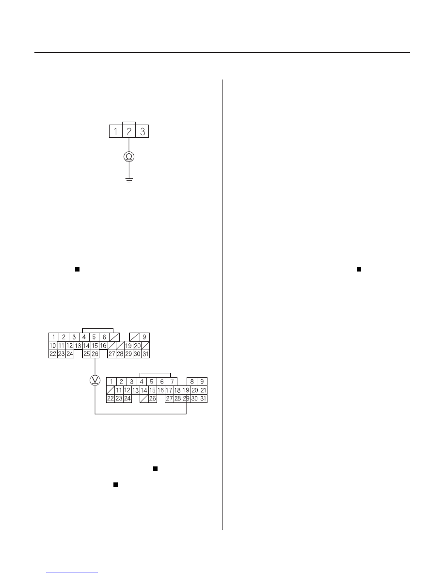
ELD 3P CONNECTOR
GND
(BLK)
PCM CONNECTORS
LG1 (BRN/BLK)
A (31P)
E (31P)
ELD (GRN/RED)
12. Check for continuity between ELD 3P connector
terminal No. 2 and body ground.
Reconnect the ELD 3P connector and PCM
connector A (31P). Go to step 13.
Repair open in the wire between the ELD and
G201.
13. Start the engine, and let it idle.
14. While measuring voltage between PCM connector
terminals A26 and E19, turn the headlights on (low).
Substitute a known-good PCM and recheck
(see page 11-5). If the symptom/indication goes
away, replace the original PCM.
Replace ELD.
1. Reset the PCM (see page 11-4).
2. Start the engine.
Go to step 3.
Intermittent failure, system is OK at this time.
Check for poor connections or loose terminals at
the TDC1/TDC2 sensor and the PCM.
3. Turn the ignition switch OFF.
4. Disconnect the TDC1/TDC2 sensor 4P connector.
TDC Sensor
1 Circuit Intermittent Interruption
TDC Sensor
1 Circuit No Signal
TDC Sensor
2 Circuit Intermittent Interruption
TDC Sensor
2 Circuit No Signal
Wire side of female terminals
Wire side of female terminals
Is ther e continuity?
Does the voltage dr op?
Is DT C P1361, P1362, P1366, or P1367
indicated?
03/07/29 09:22:48 61S0X050_110_0158