Honda Odyssey 2004. Manual - part 111
−
−
−
−
−
−
02
03
YES
NO
YES
NO
YES
NO
11-142
PGM-FI System
DTC Troubleshooting (cont’d)
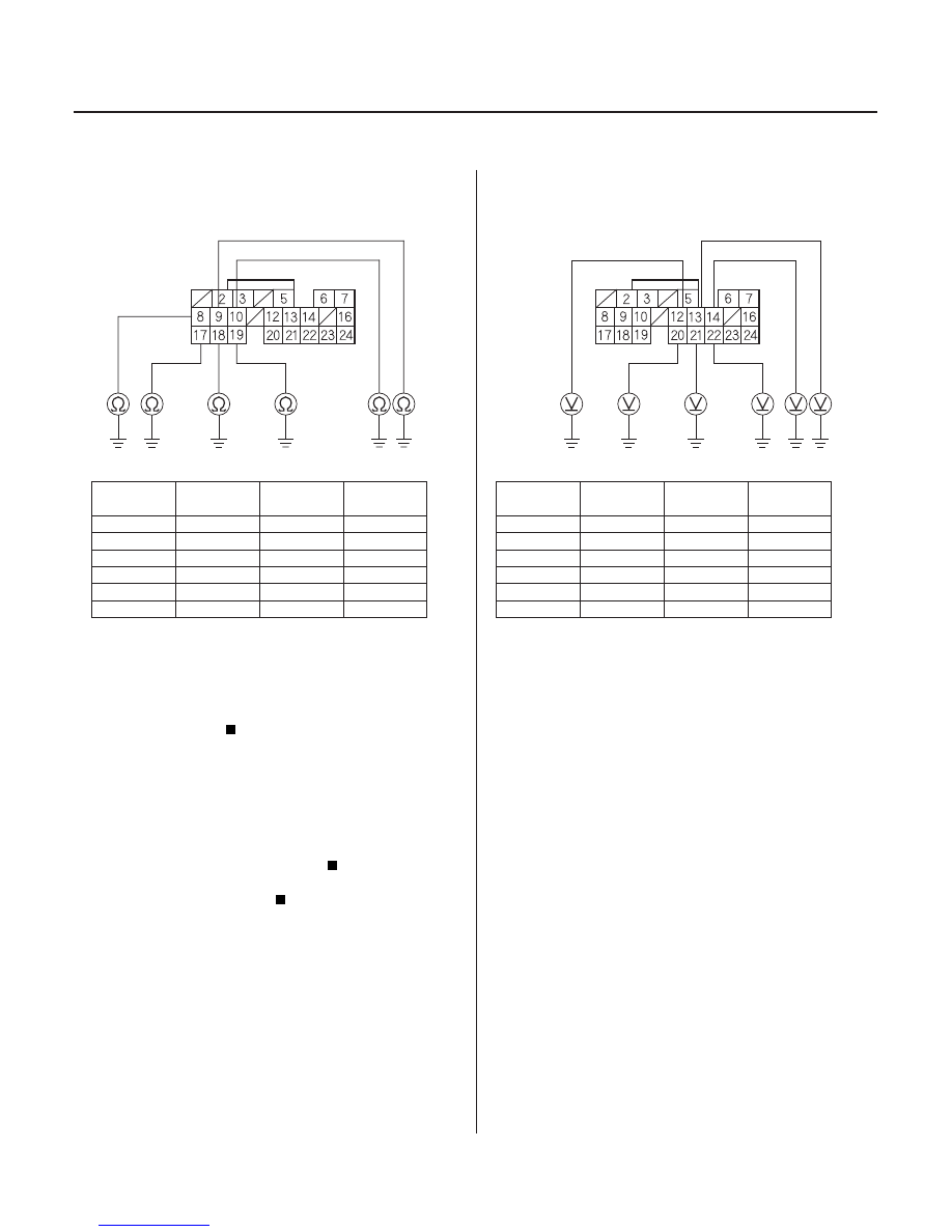
PCM CONNECTOR B (24P)
IGPLS1 (YEL/GRN)
IGPLS2 (RED)
IGPLS4 (YEL)
IGPLS6
(WHT/
BLU)
IGPLS3 (BLU)
IGPLS5
(BLK/
RED)
PCM CONNECTOR B (24P)
INJ1 (YEL)
INJ5
(BLK/
RED)
INJ6
(WHT/
BLU)
INJ3 (BLU)
INJ2 (RED)
INJ1 (BRN)
29. Check for continuity between body ground and
PCM connector terminal (see table).
PROBLEM
CYLINDER
DTC
PCM
TERMINAL
WIRE
COLOR
No. 1
P0301
B10
YEL/GRN
No. 2
P0302
B9
RED
No. 3
P0303
B8
BLU
No. 4
P0304
B19
YEL
No. 5
P0305
B18
BLK/RED
No. 6
P0306
B17
WHT/BLU
Go to step 30.
Repair open in the wire between the PCM and
the ignition coil.
30. Check the engine compression (see page 6-11).
Substitute a known-good PCM and recheck
(see page 11-5). If the symptom/indication goes
away, replace the original PCM.
Repair the engine.
31. Turn the ignition switch OFF.
32. Disconnect PCM connector B (24P).
33. Turn the ignition switch ON (II).
34. Measure voltage between body ground and the
PCM connector terminal (see table).
PROBLEM
CYLINDER
DTC
PCM
TERMINAL
WIRE
COLOR
No. 1
P0301
B14
BRN
No. 2
P0302
B13
RED
No. 3
P0303
B12
BLU
No. 4
P0304
B22
YEL
No. 5
P0305
B21
BLK/RED
No. 6
P0306
B20
WHT/BLU
Go to step 35.
Go to step 43.
35. Turn the ignition switch OFF.
36. Disconnect the injector 2P connector from the
problem cylinder.
Wire side of female terminals
Wire side of female terminals
Is ther e continuity?
Is the engine compr ession OK ?
Is ther e batter y voltage?
03/07/29 09:21:29 61S0X050_110_0142