Honda Odyssey 2004. Manual - part 100
−
−
−
−
−
−
−
−
−
*01
*02
*03
S0X4AZ0K77100090108FAAT00
DTC P0108
’99-00 Models:
YES
NO
YES
NO
YES
NO
YES
NO
11-98
PGM-FI System
DTC Troubleshooting (cont’d)
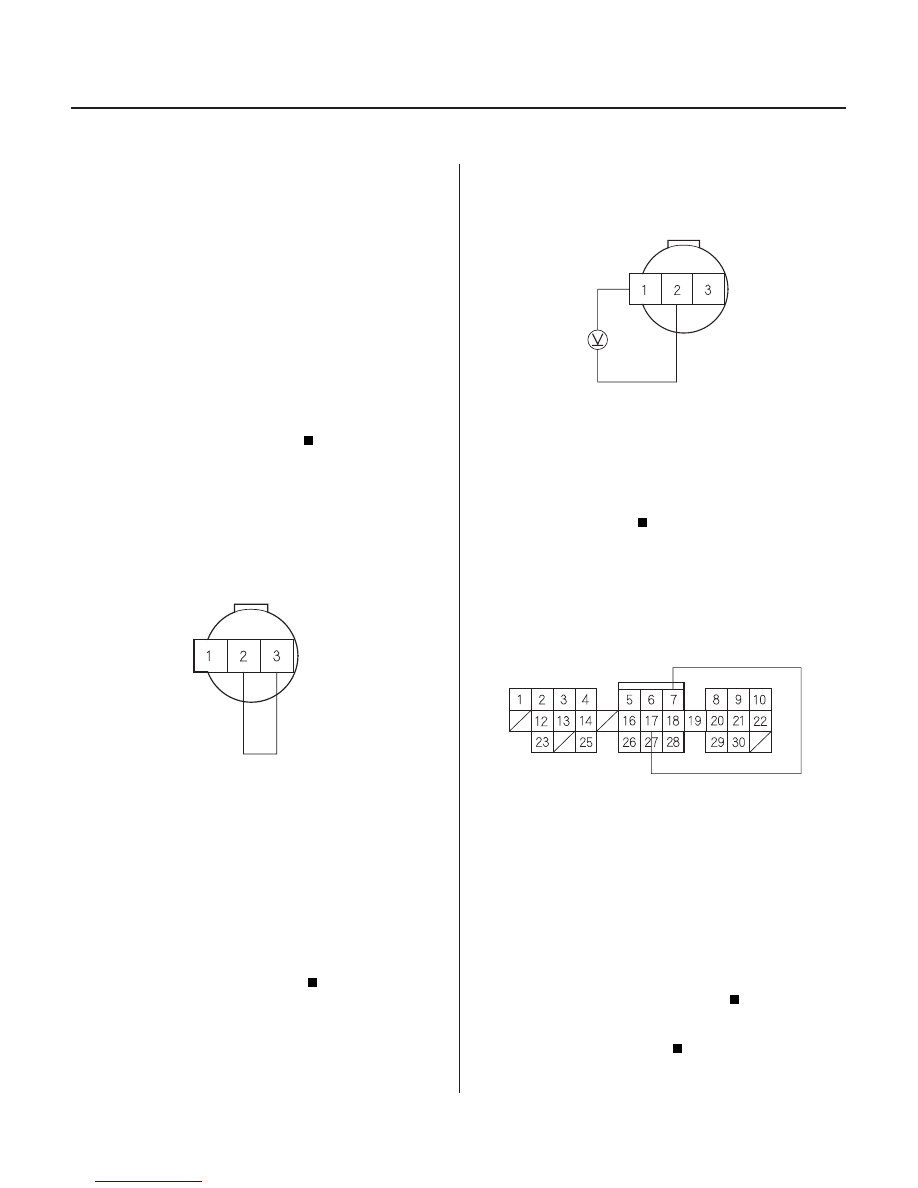
MAP SENSOR 3P CONNECTOR
MAP (RED/GRN)
JUMPER WIRE
SG1 (GRN/WHT)
MAP SENSOR 3P CONNECTOR
VCC1
(YEL/RED)
SG1 (GRN/WHT)
PCM CONNECTOR C (31P)
SG1 (GRN/WHT)
MAP (RED/GRN)
JUMPER WIRE
MAP Sensor
Circuit High Voltage
1. Start the engine. Hold the engine at 3,000 rpm with
no load (in Park or neutral) until the radiator fan
comes on, then let it idle.
2. Check the MAP with the scan tool or the HDS.
Go to step 3.
Intermittent failure, system is OK at this time.
Check for poor connections or loose terminals at
the MAP sensor and the PCM.
3. Turn the ignition switch OFF.
4. Disconnect the MAP sensor 3P connector.
5. Install a jumper wire between MAP sensor 3P
connector terminals No. 2 and No. 3.
6. Turn the ignition switch ON (II).
7. Check the MAP with the scan tool or the HDS.
Go to step 8.
Replace the MAP sensor.
8. Remove the jumper wire.
9. Measure voltage between MAP sensor 3P
connector terminals No. 1 and No. 2.
Go to step 10.
Repair open in the wire between the PCM (C7)
and the MAP sensor.
10. Turn the ignition switch OFF.
11. Connect PCM connector terminals C7 and C17 with
a jumper wire.
12. Turn the ignition switch ON (II).
13. Check the MAP with the scan tool or the HDS.
Substitute a known-good PCM and recheck
(see page 11-5). If normal MAP readings are
indicated, replace the original PCM.
Repair open in the wire between the PCM
(C17) and the MAP sensor.
Wire side of female terminals
Wire side of female terminals
Wire side of female terminals
Is mor e than 101 kPa ( 7 80 mmHg, 30 in.Hg), or
mor e than 2.9 V indicated?
Is mor e than 101 kPa ( 7 60 mmHg, 30 in.Hg), or
mor e than 2.9 V indicated?
Is ther e about 5 V ?
Is mor e than 101 kPa ( 7 60 mmHg, 30 in.Hg), or
mor e than 2.9 V indicated?
03/07/29 09:19:53 61S0X050_110_0098