Honda Odyssey 2004. Manual - part 87


  Index      Honda     Honda Odyssey 2004 - service repair manual 2004 year


Search            


Content   ..  85  86  87  88   ..


Honda Odyssey 2004. Manual - part 87


*08

*09

*10

15

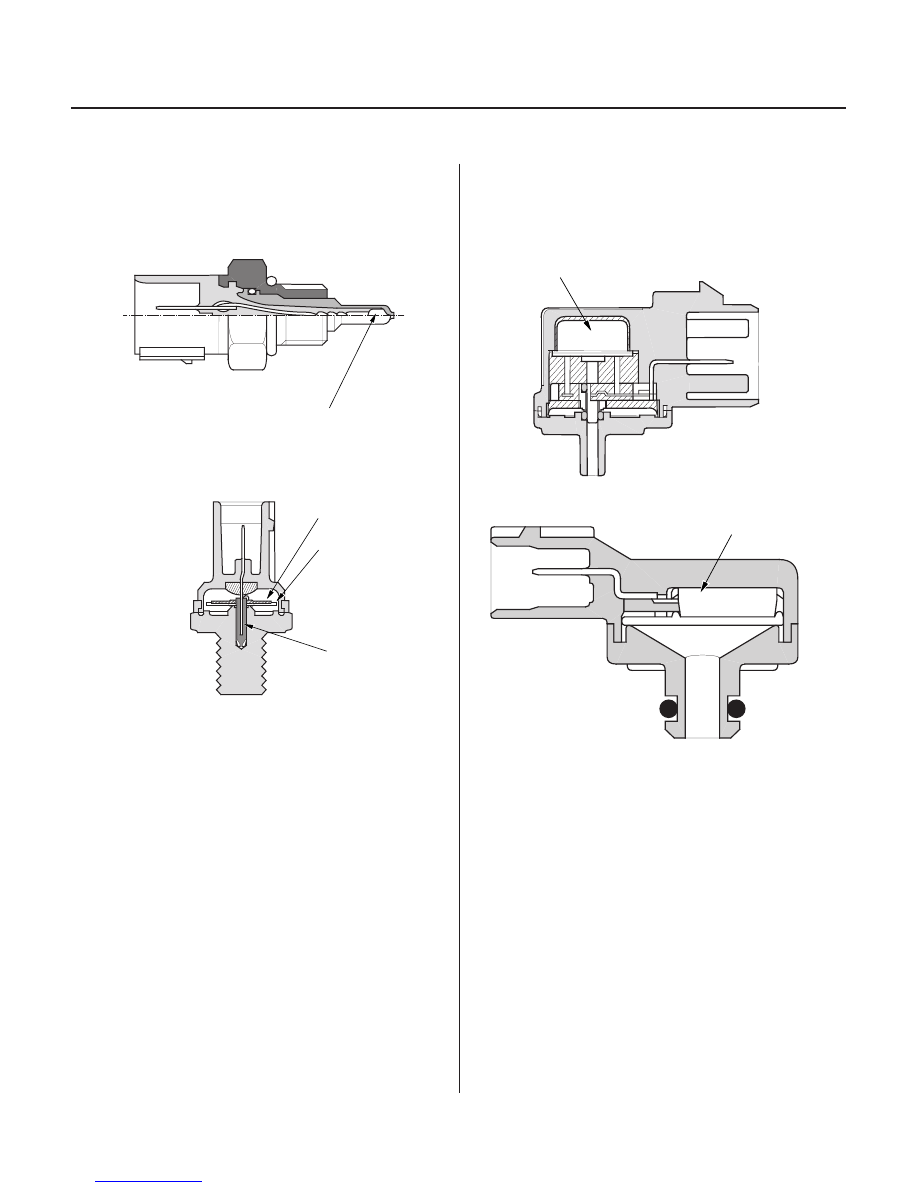
Intake Air Temperature (IAT) Sensor

Knock Sensor

Malfunction Indicator Lamp (MIL) Indication (In relation
to Readiness Codes) (’01-04 models)

Manifold Absolute Pressure (MAP) Sensor

’99-00 Models

’01-04 Models

11-46

Fuel and Emissions Systems

System Descriptions (cont’d)

THERMISTOR

PIEZO CERAMIC

DIAPHRAGM

TERMINAL

SENSOR UNIT

SENSOR UNIT

The IAT sensor is a temperature dependent resistor
(thermistor). The resistance of the thermistor decreases
as the intake air temperature increases.

The knock control system adjusts the ignition timing for
the octane rating of the gasoline used.

To check if the readiness codes are set to complete,
turn the ignition switch ON (II), but do not start the
engine. The MIL will come on for 15

20 seconds. If it

then goes off, the readiness codes are set to complete.
If it blinks several times, the readiness codes are not set
to complete. To set each code, drive the vehicle or run
the engine as described in the procedures in this
section (see page 11-89).

The MAP sensor converts manifold absolute pressure
into electrical signals to the PCM.

03/07/29 09:18:11 61S0X050_110_0046

The vehicle has certain ‘‘readiness codes’’ that are part
of the on-board diagnostics for the emissions systems.
If the vehicle’s battery has been disconnected or gone
dead, if the DTCs have been cleared, or if the PCM has
been reset, these codes are reset. In some states, part
of the emissions testing is to make sure these codes are
set to complete. If all of them are not set to complete,  
the vehicle may fail the test, or the test cannot be  
finished.

*11

*12

*13

*14

Primary Heated Oxygen Sensors (Primary HO2S)

Secondary Heated Oxygen Sensors (Secondary HO2S)

Starting Control

Throttle Position (TP) Sensor

Brake Pedal Position Switch

Idle Air Control (IAC) Valve

Idle Control System

11-47

ZIRCONIA
ELEMENT

SENSOR
TERMINALS

HEATER

HEATER
TERMINALS

ZIRCONIA
ELEMENT

SENSOR
TERMINALS

HEATER

HEATER
TERMINALS

BRUSH HOLDER

BRUSH

RESISTOR

TERMINAL

INNER
BUSHING

From AIR
CLEANER

To INTAKE
MANIFOLD

VALVE

The primary HO2S detects the oxygen content in the
exhaust gas and sends signals to the PCM which varies
the duration of fuel injection accordingly. To stabilize its
output, the sensor has an internal heater. The primary
HO2S is installed in the exhaust pipe.
By controlling the air fuel ratio with primary HO2S and
secondary HO2S, the deterioration of the primary HO2S
can be evaluated by its feedback period. When the
feedback period exceeds a certain value during stable
driving conditions, the sensor is considered
deteriorated and the PCM sets a DTC.

The secondary HO2S detects the oxygen content in the
exhaust gas downstream of the three way catalytic
converter (TWC) and sends signals to the PCM which
varies the duration of fuel injection accordingly. To
stabilize its output, the sensor has an internal heater.
The secondary HO2S is installed in the TWC.

When the engine is started, the PCM provides a rich
mixture by increasing fuel injector duration.

The TP sensor is a potentiometer connected to the
throttle valve shaft. As the throttle position changes, the
sensor varies the signal voltage to the PCM. The TP
sensor is not available separately from the throttle body.

When the engine is cold, the A/C compressor is on, the
transmission is in gear, the brake pedal is pressed, the
power steering load is high, or the alternator is
charging, the PCM controls current to the IAC valve to
maintain the correct idle speed. Refer to the System
Diagram to see a functional layout of the system.

The BPP switch signals the PCM when the brake pedal
is pressed.

To maintain proper idle speed, the IAC valve changes
the amount of air bypassing the throttle body in
response to an electrical signal from the PCM.

(cont’d)

03/07/29 09:18:12 61S0X050_110_0047

*15

06

Power Steering Pressure (PSP) Switch

Starter (Ignition) Switch

Fuel Cut-off Control

Fuel Pump Control

Fuel Gauge Sending Unit

PGM-FI Main Relay

Heated Air Induction System

Fuel Supply System

Intake Air System

11-48

Fuel and Emissions Systems

System Descriptions (cont’d)

’03-04 models

YEL/BLU

BLK

To GAUGE
ASSEMBLY

FUEL TANK

FUEL GAUGE SENDING UNIT

AIR TEMPERATURE
CONTROL VALVE

AIR VALVE

The PSP switch signals the PCM when the power
steering load is high.

The starter switch signals the PCM when the engine is
cranking.

During deceleration with the throttle valve closed,
current to the injectors is cut off to improve fuel
economy at engine speeds over 1,100 rpm.
Fuel cut-off action also occurs when engine speed
exceeds 6,600 rpm, regardless of the position of the
throttle valve, to protect the engine from over-revving.
When the vehicle is stopped, the PCM cuts the fuel at
engine speeds over 5,000 rpm.

When the ignition is turned on, the PCM grounds the
PGM-FI main relay which feeds current to the fuel pump
for 2 seconds to pressurize the fuel system. With the
engine running, the PCM grounds the PGM-FI main
relay and feeds current to the fuel pump. When the
engine is not running and the ignition is on, the PCM
cuts ground to the PGM-FI main relay which cuts
current to the fuel pump.

The fuel gauge sending unit measures the fuel level in
the fuel tank. The fuel gauge sending unit output
changes according to the float position.

The PGM-FI relay contains 2 separate relays. One is
energized whenever the ignition is on which supplies
battery voltage to the PCM, power to the fuel injectors,
and power for the second relay. The second relay is
energized to supply power to the fuel pump for
2 seconds when the ignition is switched ON (II), during
engine cranking, and when the engine is running.

Refer to the System Diagram to see a functional layout
of the system.

The heated air induction system improves fuel
economy in cold weather conditions and when the
engine is cold.
When outside air temperature is low, the air
temperature control valve opens the air valve to allow
heated air into the engine.

03/07/29 09:18:13 61S0X050_110_0048

16

30

26

25

Intake Air Bypass Control Thermal Valve

Throttle Body

Three Way Catalytic Converter (TWC)

EGR Valve

Catalytic Converter System

Exhaust Gas Recirculation (EGR) System

Positive Crankcase Ventilation (PCV) System

11-49

INJECTOR

INTAKE
AIR

:

To
INJECTORS

To FUEL
INJECTORS

From
AIR
CLEANER

VALVE

INTAKE AIR
BYPASS
CONTROL
THERMAL
VALVE

IDLE ADJUSTING
SCREW

THROTTLE
POSITION (TP)
SENSOR

FRONT
OF
VEHICLE

THREE WAY
CATALYSTS

HOUSING

INTAKE
MANIFOLD

BREATHER
PIPE

PCV
HOSE

PCV
VALVE

: BLOW-BY VAPOR

: FRESH AIR

When the engine is running, the intake air bypass
control thermal valve sends air to the injectors.

The throttle body is a single-barrel side draft type. The
lower portion of the throttle valve is heated by engine
coolant from the cylinder head. The idle adjusting
screw, which increases/decreases bypass air, is on top
of the throttle body.

The TWC converts hydrocarbons (HC), carbon
monoxide (CO), and oxides of nitrogen (NOx) in the
exhaust gas to carbon dioxide (CO2), nitrogen (N2), and
water vapor.

Refer to the System Diagram to see a functional layout
of the system.

The EGR valve is designed to lower peak combustion
temperatures and reduce oxides of nitrogen emissions
(NOx) by recirculating exhaust gas through the intake
manifold and into the combusition chambers.

The PCV valve prevents blow-by gasses from escaping
into the atmosphere by venting them into the intake
manifold.

(cont’d)

03/07/29 09:18:14 61S0X050_110_0049


Content   ..  85  86  87  88   ..