Honda Odyssey 2004. Manual - part 75


  Index      Honda     Honda Odyssey 2004 - service repair manual 2004 year


Search            


Content   ..  73  74  75  76   ..


Honda Odyssey 2004. Manual - part 75


02

S0X4A00A14426149101FAAT33

03

S0X4A00A14426149101FAAT41

YES
NO

YES
NO

YES

NO

YES
NO

YES

NO

10-24

10-24

Fan Controls

Radiator and Condenser Fan Circuit
Troubleshooting C

Radiator and Condenser Fan High
Speed Circuit Troubleshooting

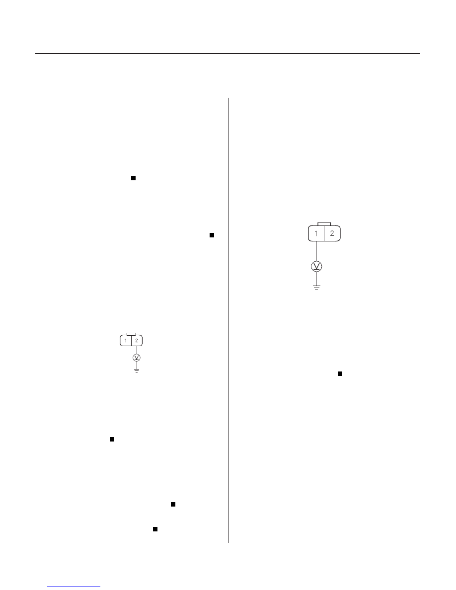
RADIATOR FAN MOTOR 2P CONNECTOR

BLU/BLK

RADIATOR FAN SWITCH B 2P CONNECTOR

BLU/RED

NOTE: Refer to the symptom troubleshooting index
before troubleshooting.

1. Remove the condenser fan relay, and test it (see

page 22-88).

Go to step 2.

Replace the relay.

2. Disconnect radiator fan switch B 2P connector and

turn the ignition switch ON (II).

Replace radiator fan switch B and recheck.

Go to step 3.

3. Turn the ignition switch OFF.

4. Remove the radiator fan relay from the under-hood

fuse/relay box.

5. Check for continuity between radiator fan switch B

2P connector terminal No. 1 and body ground.

Repair a short in the wire between radiator

fan relay 4P socket terminal No. 3, radiator fan
switch B 2P connector terminal No. 1 and A/C
pressure switch.

Go to step 6.

6. Disconnect the radiator fan switch A 2P connector

and turn the ignition switch ON (II).

Replace radiator fan switch A.

Repair a short in the wire between radiator

fan relay 4P socket terminal No. 3, condenser fan
relay 4P socket terminal No. 3.

NOTE: Refer to the symptom troubleshooting index
before troubleshooting.

1. Remove the radiator fan relay and condenser fan

relay from the under-hood fuse/relay box.

2. Disconnect the radiator fan switch B 2P connector.

3. Turn the ignition switch ON (II).

4. Measure the voltage between radiator fan switch B

2P connector terminal No. 1 and body ground.

Go to step 5.

Repair an open in the wire between fan

control relay 5P socket terminal No. 3 and radiator
fan switch B terminal No. 1.

5. Install the radiator fan relay and condenser fan

relay.

Wire side of female terminals

Wire side of female terminals

Is the r elay OK ?

Does the r adiator f an stop?

Is ther e continuity?

Does the r adiator f an stop?

Is ther e the batter y voltage?

03/07/29 09:15:25 61S0X050_100_0024

04

01

*01

S0X4A00A14426149451FEAT00

YES

NO

10-25

10-25

Radiator Fan Switch Test

RADIATOR FAN SWITCH B 2P CONNECTOR

BLK

BLU/RED

JUMPER
WIRE

B

1

2

A

WATER

Terminal

Operation

A

B

ON

OFF

ON

OFF

SWITCH

A

SWITCH

B

Temperature

196

203°F

(91

95°C)

5

15°F (3

8°C) lower

than the temperature
when it goes on

205

216°F

(96

102°C)

5

18° (3

10°) lower

than the temperature
when it goes on

6. Connect a jumper wire between radiator fan switch

B 2P connector terminals No. 1 and No. 2.

7. Turn the ignition switch ON (II).

Replace radiator fan switch B.

Repair an open in the wire between radiator

fan switch B 2P connector terminal No. 2 and
ground G101.

1. Remove radiator fan switch A from the water

passage and radiator fan switch B from the cylinder

2. Suspend each radiator fan switch (A) in a container

of coolant as shown.

3. Heat the coolant and check the temperature with a

thermometer (B). Do not let the thermometer touch
the bottom of the hot container.

4. Measure the continuity between terminal (No. 1)

and terminal (No. 2) according to the table.

5. Replace, if necessary, and install the radiator fan

switches.

Wire side of female terminals

Do the r adiator and condenser f ans r un?

03/07/29 09:15:26 61S0X050_100_0025

head (see page 10-4).

S0X4A000000000J1001ZAAT00

03/07/29 09:15:26 61S0X050_100_0026

S0X4A000000000J1101ZCAT00

Fuel and Emissions

Fuel and Emissions Systems

PGM-FI System

Idle Control System

Fuel Supply System

Intake Air System

Catalytic Converter System

EGR System

PCV System

EVAP System

...........................

..........................

...

.....................................

...............

.

...........................

..........................

...

.....................................

...............

.

Special Tools

. 11-2

General Troubleshooting

Information

. 11-3

DTC Troubleshooting Index

. 11-6

Symptom Troubleshooting

Index

. 11-9

System Descriptions

. 11-10

How to Set Readiness Codes . 11-89

...

.............

..

.

..............

..

........................

...

.............

..

.

..............

..

........................

Component Location Index

. 11-92

DTC Troubleshooting

. 11-95

MIL Circuit Troubleshooting

. 11-166

DLC Circuit Troubleshooting

. 11-173

Injector Replacement

. 11-177

Primary HO2S Replacement

. 11-181

Secondary HO2S

Replacement

. 11-181

...

.............

..................

..................

..................

..................

..

...........

.....

...

.............

..................

..................

..................

..................

..

...........

.....

Component Location Index

. 11-182

DTC Troubleshooting

. 11-183

A/C Signal Circuit

Troubleshooting

. 11-188

Alternator FR Signal Circuit

Troubleshooting

. 11-192

Starter Switch Signal Circuit

Troubleshooting

. 11-195

PSP Switch Signal Circuit

Troubleshooting

. 11-196

. 11-199

Idle Speed Adjustment

. 11-201

PCM Idle Learn Procedure

. 11-202

...

.............

..................

..........

..................

.......................

................

................

...................

...

.............

..................

..........

..................

.......................

................

................

...................

Component Location Index

. 11-203

DTC Troubleshooting

. 11-205

PGM-FI Main Relay Circuit

Troubleshooting

. 11-209

Fuel Pressure Relieving

. 11-215

Fuel Pressure Test

. 11-216

Fuel Pump Test

. 11-218

Fuel Line Inspection

. 11-219

Fuel Tube/Quick-Connect

Fitting Precaution

. 11-223

Fuel Tube/Quick-Connect

Fitting Removal

. 11-224

...............

........................

..........

........

..........

......................

...............

.......

...............

........................

..........

........

..........

......................

...............

.......

Fuel Tube/Quick-Connect

Fitting Installation

. 11-225

Fuel Pressure Regulator

Replacement

. 11-227

Fuel Filter Replacement

. 11-229

Fuel Pump Replacement

. 11-230

Fuel Tank Replacement

. 11-231

Fuel Gauge Test

. 11-233

Fuel Gauge Sending Unit

Test/Replacement

. 11-234
. 11-235

...

..................

..........

.............

.........................

........................

..

.....

...........................

.........................

...

..................

..........

.............

.........................

........................

..

.....

...........................

.........................

Component Location Index

. 11-236

Throttle Body Test

. 11-237

Throttle Body Cleaning

. 11-237

Intake Air Bypass Control

Thermal Valve Test

. 11-238

Heated Air Induction

System Test

. 11-239

Air Cleaner Element

Replacement

. 11-240

Air Cleaner Housing

Disassembly/Reassembly

. 11-241

Throttle Cable Adjustment

. 11-242

Throttle Body Removal/

Installation

. 11-243

Throttle Body Disassembly/

Reassembly

. 11-245

.............

.............

DTC Troubleshooting

. 11-246

.............

.............

DTC Troubleshooting

. 11-247

.......................................

.......................................

PCV Valve Inspection and

Test

. 11-257

...

.............

.....

............................

........................

...

.............

.....

............................

........................

Component Location Index

. 11-258

DTC Troubleshooting

. 11-261

EVAP Two Way Valve Test

. 11-297

Fuel Tank Vapor Control

Valve Test

. 11-298

Fuel Tank Vapor Control Valve

Replacement

. 11-301

Brake Pedal Position Switch

Signal Circuit Troubleshooting

Low Fuel Indicator Light Test

03/07/29 09:17:42 61S0X050_110_0001


Content   ..  73  74  75  76   ..