Honda Odyssey 2004. Manual - part 38
05
01
07
08
5-14
Engine Assembly
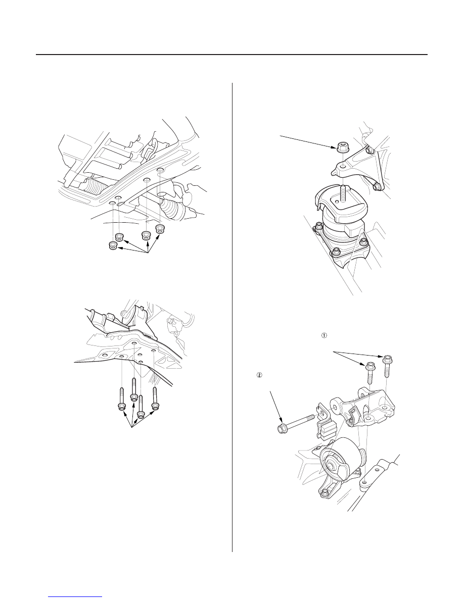
Engine Installation (cont’d)
10 x 1.25 mm
38 N·m (3.9 kgf·m,
28 lbf·ft)
10 x 1.25 mm
42 N·m (4.3 kgf·m,
31 lbf·ft)
12 x 1.25 mm
54 N·m (5.5 kgf·m,
40 lbf·ft)
12 x 1.25 mm
54 N·m (5.5 kgf·m,
40 lbf·ft)
10 x 1.25 mm
44 N·m (4.5 kgf·m,
33 lbf·ft)
5. Install the transmission lower front mount and
transmission lower rear mount on the front
subframe.
6. Install the rear mount on the front subframe.
7. Lower the hoist.
8. Tighten the front mount bracket support nut.
9. Install the side engine mount bracket, then tighten
the mounting bolts in the numbered sequence
shown.
10. Remove the chain hoist from the engine.
03/07/29 09:09:20 61S0X050_050_0014