Honda Odyssey 2004. Manual - part 30


  Index      Honda     Honda Odyssey 2004 - service repair manual 2004 year


Search            


Content   ..  28  29  30  31   ..


Honda Odyssey 2004. Manual - part 30


*05

*06

*07

*08

4-40

Charging System

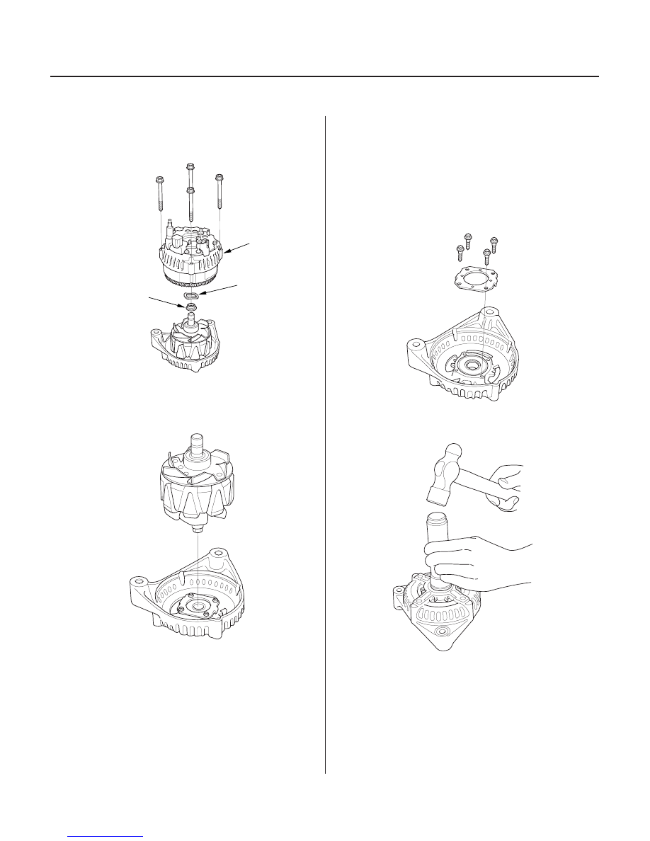
Alternator Overhaul (cont’d)

A

B

C

7. Remove the four bolts, then remove the rear

housing assembly (A), washer (B), and rear bearing
cover (C).

8. If you are not replacing the front bearing and/or

rear bearing, go to step 15. Otherwise, remove the
rotor from the drive end housing.

9. Inspect the rotor shaft for galling, and inspect the

bearing journal surface in the drive end housing for
seizure marks.

• If the rotor is damaged, replace the rotor

assembly.

• If the rotor is OK, go to step 10.

10. Remove the front bearing retainer plate.

11. Drive out the front bearing with a brass drift and

hammer.

03/07/29 09:08:17 61S0X050_040_0040

*09

*10

*11

Alternator Brush Inspection

Alternator Brush Length
Standard (New): 10.5 mm (0.41 in.)
Service Limit:

1.5 mm (0.06 in.)

Rotor Slip Ring Test

4-41

07749-0010000

07746-0010300

B

A

A

B

C

12. With a hammer and special tools, install a new

front bearing in the drive end housing.

13. Measure the length of both brushes (A) with vernier

calipers (B).

• If either brush is shorter than the service limit,

replace the brush holder assembly.

• If the brush length is OK, go to step 14.

14. Check that there is continuity between the slip rings

(A).

• If there is continuity, go to step 15.
• If there is no continuity, replace the rotor

assembly.

15. Check that there is no continuity between each slip

ring and the rotor (B) and the rotor shaft (C).

• If there is no continuity, replace the rear housing

assembly, and go to step 16.

• If there is continuity, replace the rotor assembly.

16. Reassemble the alternator in reverse order of

disassembly, and note these items:

• Be careful not to get any grease or oil on the slip

rings.

• If you removed the pulley, tighten its locknut to

111 N·m (11.3 kgf·m, 81.7 lbf·ft) when you
reinstall it.

03/07/29 09:08:17 61S0X050_040_0041

*01

S0X4A08A14500000000DAAT00

4-42

Cruise Control

Component Location Index

BRAKE PEDAL POSITION SWITCH

MAIN SWITCH

CRUISE CONTROL INDICATOR
(Built into gauge assembly)

SET/RESUME/CANCEL
SWITCH

CRUISE CONTROL UNIT

CRUISE CONTROL ACTUATOR

ACTUATOR CABLE

TRANSMISSION RANGE SWITCH

Test, page 4-51
Pedal Height Adjustment,

page 19-6

Test:

1999-2001 models, page 4-50
2002-2004 models, page 4-50

Replacement:

1999-2001 models, page 4-50
2002-2004 models, page 4-50

Test, page 4-51
Replacement,

page 4-51

Input Test, page 4-48

Adjustment, page 4-52

Test:

1999-2001 models, page 14-173
2002-2004 models, page 14-403

03/07/29 09:08:20 61S0X050_040_0042

*01

S0X4A08A14500000000EAAT00

4-43

Circuit Diagram

1

2

G501

WHT/YEL

2

3

BLK

4

3

G101

BLU/GRN

BLK

BLK

BLK

LT BLU

BRN

BRN/BLK

BRN/WHT

CRUISE CONTROL UNIT

DIMMING CIRCUIT

SET

WHT/BLK

GRY

LT GRN

LT GRN

BLU/BLK

RED/BLK

LT GRN/RED

LT GRN/BLK

4

3

BLK/YEL

RED/BLK

RED/BLK

RED

BLK

LT GRN

BLK/YEL

No.41 (120A)

BATTERY

IGNITION SWITCH

IG1

BAT

UNDER HOOD FUSE/RELAY BOX

No.42 (50A)

WHT

PCM

(15A)

No.6

(20A)

No.47

2

1

2

1

5

BLU/RED

HORN

5

2

6

7

13

9

11

1

14

3

BLK

10

LT GRN/BLU

HORN SWITCH

12

BLU/WHT

4

BLK/YEL

PCM

No.9 (10A)

YEL

BLK/YEL

BLK

G201

1

4

3

8

CRUISE
CONTROL
MAIN
SWITCH

(5)

(4)

(7)

(2)

(2)

( ) : 2002 2004models

IG1 HOT in ON (II)
and START (III)

DRIVER’S UNDER DASH
FUSE/RELAY BOX

COMBINATION
LIGHT SWITCH

INDICATOR
(0.84W)

LIGHT
(0.84W)

HORN
RELAY

CABLE
REEL

CRUISE
CONTROL
SET/
CANCEL
RESUME
SWITCH

RE
SUME

CAN
CEL

BRAKE PEDAL
POSITION
SWITCH

DRIVER’S
UNDER DASH
FUSE/RELAY
BOX

GAUGE
ASSEMBLY

CABLE
REEL

CRUISE
INDICATOR
(1.2W)

GAUGE
ASSEMBLY

CRUISE CONTROL
ACTUATOR

TRANSMISSION
RANGE
SWITCH

ON : 2, D3, D4

03/07/29 09:08:21 61S0X050_040_0043


Content   ..  28  29  30  31   ..